
Ocean surface wind field measurement method based on shipborne high frequency ground wave radar

A high-frequency ground wave radar and measurement method technology, applied in radio wave measurement systems, measurement devices, reflection/re-radiation of radio waves, etc., can solve problems such as inability to measure large areas, difficult deployment and maintenance, and limited measurement performance. , to overcome the limitations of wind speed measurement, expand the detection range, and overcome the effects of large scale

Active Publication Date: 2018-05-08
HARBIN INST OF TECH
View PDF7 Cites 4 Cited by
  • Summary
  • Abstract
  • Description
  • Claims
  • Application Information

AI Technical Summary

Problems solved by technology

[0005] The purpose of the present invention is to solve the problems of difficult deployment and maintenance of traditional ocean surface wind field measurement tools, inability to measure large areas and low observation efficiency; and the problem of shore-based high-frequency ground wave radar detection of sea areas and limited measurement performance, and propose a Ocean Surface Wind Field Measurement Method Based on Shipborne High Frequency Surface Wave Radar

Method used


Image

  • Ocean surface wind field measurement method based on shipborne high frequency ground wave radar
  • Ocean surface wind field measurement method based on shipborne high frequency ground wave radar
  • Ocean surface wind field measurement method based on shipborne high frequency ground wave radar

Examples


specific Embodiment approach 1

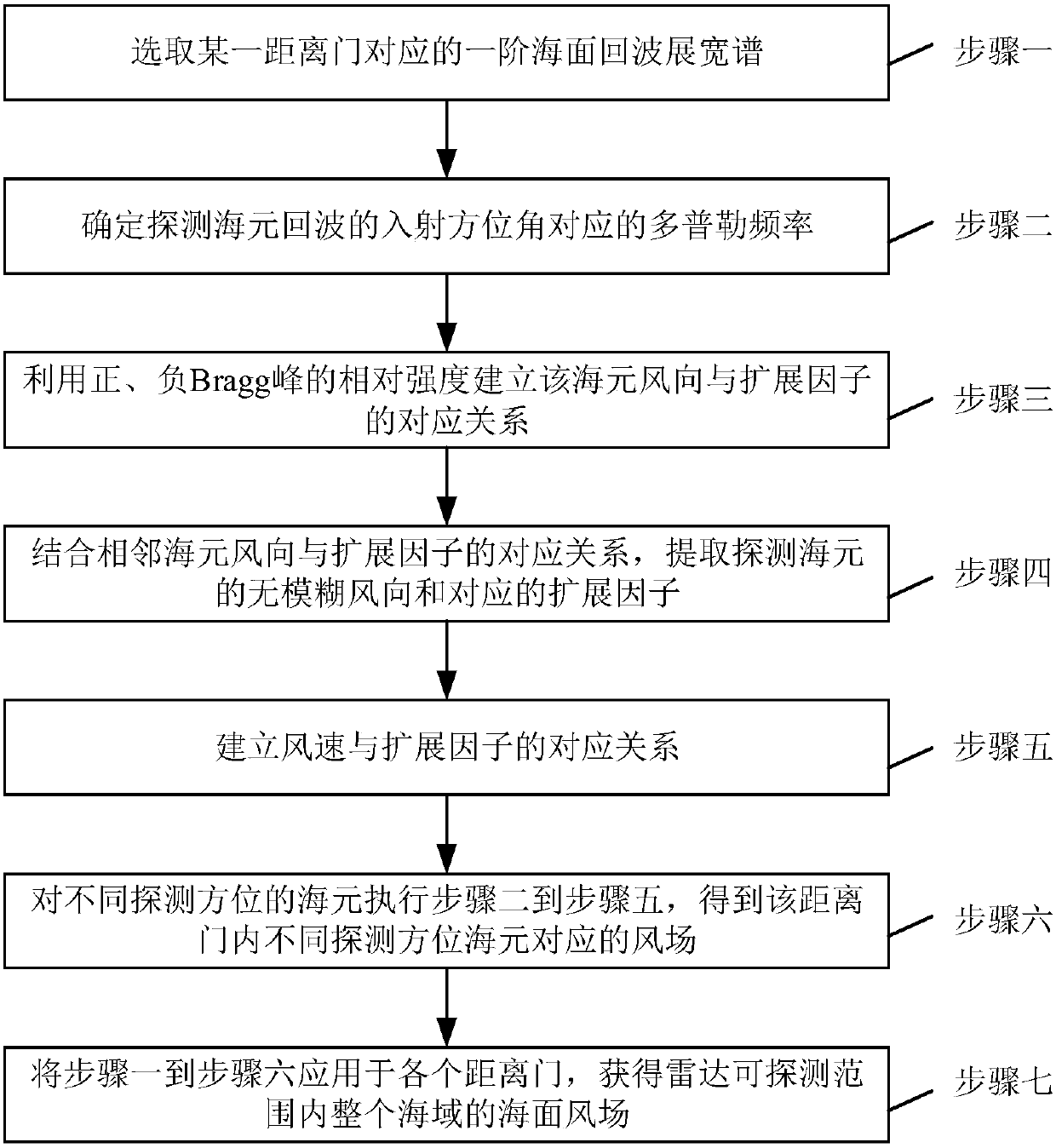
[0033] Specific implementation mode one: combine figure 1 To illustrate this embodiment, the specific process of a method for measuring ocean surface wind field based on ship-borne high-frequency ground wave radar described in this embodiment is as follows:

[0034] Step 1: Select the first-order sea echo Doppler broadening spectrum corresponding to a certain range gate;

[0035] Step 2: Divide the detected sea area at equal intervals according to the distance resolution of the radar system, and then divide the detected sea area based on the Doppler beam sharpening technology to obtain a grid map of the detected sea area, where each grid is called as an ocean unit;

[0036] Based on step 1, determine the Doppler frequency corresponding to the incident azimuth angle of the ocean unit echo of the detected azimuth;

[0037] Step 3: Based on Step 2, use the relative strength of the positive and negative Bragg (Bragg) peaks to establish the correspondence between the wind direct...

specific Embodiment approach 2

[0044] Specific embodiment two: the difference between this embodiment and specific embodiment one is: the first-order sea surface echo Doppler broadening spectrum corresponding to a certain range gate is selected in the step one, and the specific process is:

[0045] 1) Using the moving ship-borne platform and a single receiving array element to obtain the sea surface echo range-Doppler spectrum, the maximum moving speed of the ship-borne platform is Where g is the acceleration due to gravity, and λ is the wavelength of the electromagnetic wave;

[0046] 2) According to the system distance resolution of the ship-borne high-frequency ground wave radar, the detected sea area is divided into N range gates at equal intervals, where ρ max is the maximum detection range of the shipborne high-frequency ground wave radar, ΔR is the system distance resolution of the radar, is the rounding down symbol;

[0047] 3) Select the first-order sea echo Doppler broadening spectrum σ corr...

specific Embodiment approach 3

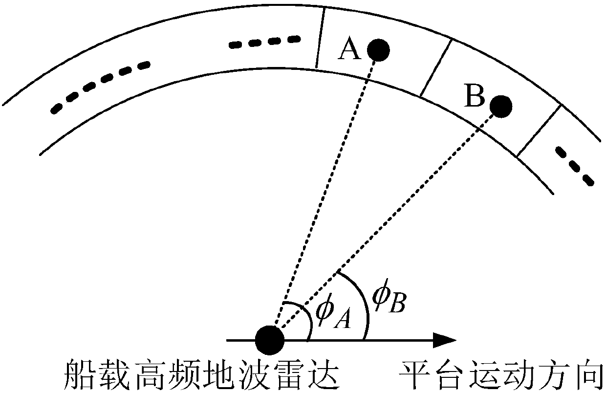
[0049] Specific embodiment three: the difference between this embodiment and specific embodiment one or two is: the Doppler frequency corresponding to the incident azimuth angle of the ocean unit echo of the detected azimuth is determined in the step two, and the specific process is:

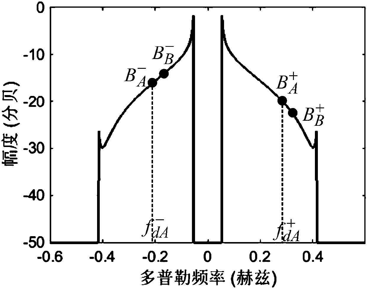
[0050] Let φ A is the incident azimuth angle of the echo detected at ocean unit A, and is the angle between the movement direction of the ship-borne platform and the echo of the ocean unit, where φ A ∈[0,π], through the relation Obtain the incident azimuth φ of the echo at the detection ocean unit A A The corresponding positive and negative Doppler frequencies are and

[0051] in is the first-order Bragg frequency of the shore-based high-frequency surface wave radar, and v is the velocity of the ship-borne platform.

[0052] Other steps and parameters are the same as those in Embodiment 1 or Embodiment 2.


PUM


Abstract

The invention discloses an ocean surface wind field measurement method based on a shipborne high frequency ground wave radar and relates to an ocean surface wind field measurement method. The problemsthat a traditional ocean surface wind field measurement tool is difficult to deploy and maintain, a large area cannot be measured and the observation efficiency is low are solved, and the problem that the detection ocean area and measurement performance of a shore-based high frequency surface wave radar are limited is solved. The method comprises the steps of (1) selecting first-order ocean surface echo Doppler broadening spectrum corresponding to a distance gate, (2) determining a Doppler frequency corresponding to an incident azimuth of ocean unit echo of a detected azimuth, (3) establishing a corresponding relation between a wind direction and an expansion factor, (4) extracting an unambiguous wind direction and a corresponding expansion factor, (5) establishing a corresponding relation between a wind speed and an expansion factor, (5) repeating steps (2), (3), (4) and (5) and orderly obtaining wind fields corresponding to different detection azimuths in the distance gate, and (7)repeating steps (1), (2), (3), (4), (5) and (6) for N times and obtaining an ocean surface wind field of a whole ocean area within a radar detection range. The method is used in the field of wind field measurement of the ocean surface.

Description

technical field [0001] The invention relates to a method for measuring ocean surface wind field. Background technique [0002] Among the dynamic parameters of the ocean surface, the sea surface wind is an important factor in the study of energy and material exchange between the atmosphere and the ocean, an active factor affecting elements such as waves and currents, and one of the key objects of oceanographic research. It has an important influence on the development of marine resources, weather forecasting and oceanographic research. However, traditional ocean surface wind field measurement tools are difficult to deploy and maintain, unable to measure large areas and have low observation efficiency. [0003] The operating frequency of high-frequency ground wave radar is 3-30MHz. High-frequency ground wave radar uses the characteristics of good diffraction and small attenuation of vertically polarized electromagnetic waves along the sea surface, which can break through the ...

Claims


Application Information

Patent Timeline
IPC IPC(8): G01S13/95
CPCG01S13/956Y02A90/10
Inventor 谢俊好姚国伟席堃冀振元
Owner HARBIN INST OF TECH
Learn More