Spin polarized current generator and magnetic device thereof
A technology of current generator and spin polarization, which is applied to parts of electromagnetic equipment, resistors controlled by magnetic fields, instruments, etc., which can solve the problems of reducing device reliability, writing failure, and high energy consumption of writing data, etc. , to improve reliability and stability, reduce resistivity, and reduce energy consumption
- Summary
- Abstract
- Description
- Claims
- Application Information
AI Technical Summary
Problems solved by technology
Method used
Image

Examples
Embodiment Construction
[0054] The following exemplary embodiments relate to circuits and devices with magnetic materials or structures and their applications, more specifically, spin-polarized current generators and their magnetic devices, but are not intended to serve as a basis for any limitation of the present invention.
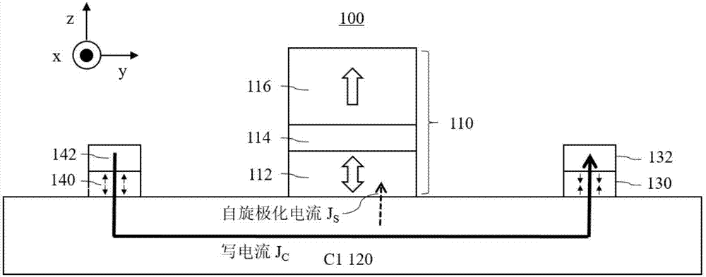
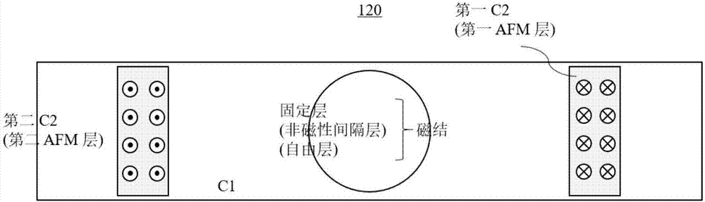
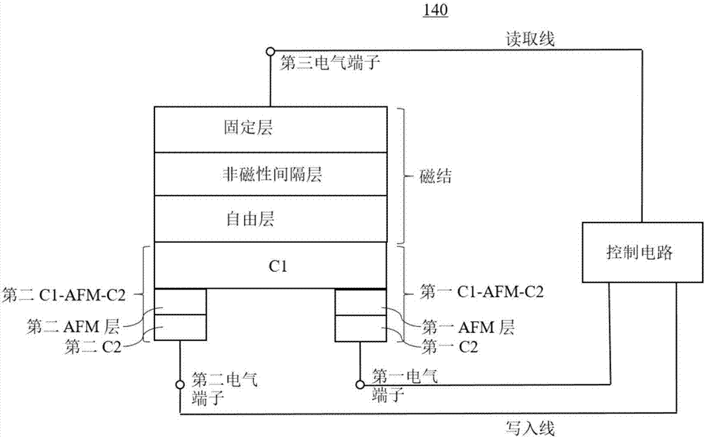
[0055] Figure 1A Showing a magnetic device according to one embodiment of the present disclosure, for clarity, Figure 1A and any other illustrations of the invention are not drawn to scale. The magnetic device is a three-terminal magnetic memory described by using the "first conductive layer-antiferromagnetic layer-second conductive layer" (called "C1-AFM-C2") asymmetric stack structure as a spin-polarized current generator bit cell 100. The magnetic device includes a first conductive layer C1 120, and two antiferromagnetic layers (AFM layers) on the first conductive layer C1 120 (ie, the second antiferromagnetic layer 140, the first antiferromagnetic layer 130) and the seco...
PUM
| Property | Measurement | Unit |
|---|---|---|
| Thickness | aaaaa | aaaaa |
| Thickness | aaaaa | aaaaa |
Abstract
Description
Claims
Application Information
 - Generate Ideas
- Intellectual Property
- Life Sciences
- Materials
- Tech Scout
- Unparalleled Data Quality
- Higher Quality Content
- 60% Fewer Hallucinations
Browse by: Latest US Patents, China's latest patents, Technical Efficacy Thesaurus, Application Domain, Technology Topic, Popular Technical Reports.
© 2025 PatSnap. All rights reserved.Legal|Privacy policy|Modern Slavery Act Transparency Statement|Sitemap|About US| Contact US: help@patsnap.com