Reflective intensity modulation (RIM) optical fiber sensor unequally spaced misalignment type compensation structure

An optical fiber sensor and intensity modulation technology, applied in instruments, optical devices, measuring devices, etc., can solve the problems of different reflectivity, optical fiber transmission loss measurement system error, etc., and achieve the goal of improving measurement linearity, improving performance, and eliminating range Effect

Inactive Publication Date: 2018-05-11
ZHONGBEI UNIV
View PDF5 Cites 3 Cited by
  • Summary
  • Abstract
  • Description
  • Claims
  • Application Information

AI Technical Summary

Problems solved by technology

In addition, the reflectivity of the reflective surface is different, and the optical fiber transmission loss will cause a certain error to the measurement system; therefore, to improve the measurement accuracy of the system, it is necessary to adopt intensity compensation technology to eliminate the interference of environmental factors

Method used


Image

  • Reflective intensity modulation (RIM) optical fiber sensor unequally spaced misalignment type compensation structure
  • Reflective intensity modulation (RIM) optical fiber sensor unequally spaced misalignment type compensation structure
  • Reflective intensity modulation (RIM) optical fiber sensor unequally spaced misalignment type compensation structure

Examples


specific Embodiment

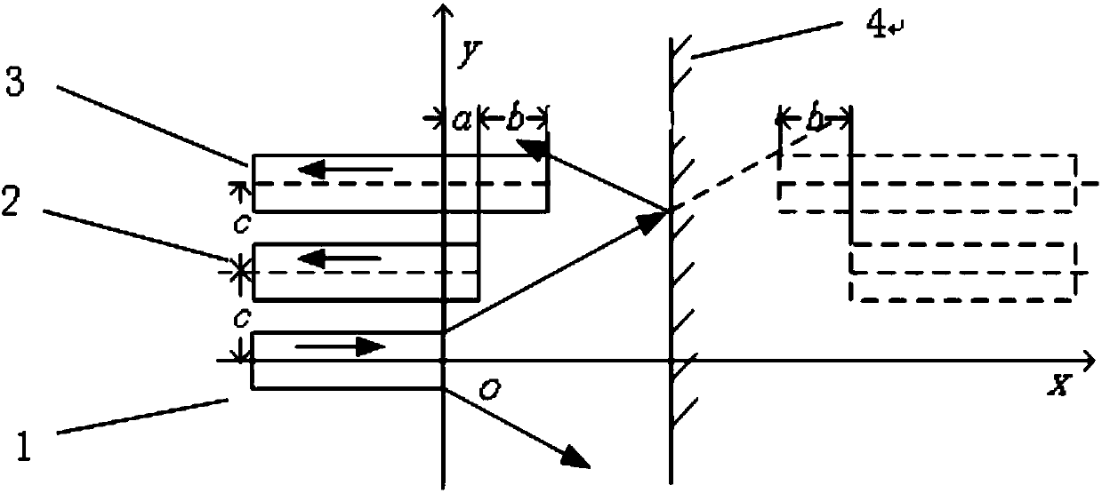
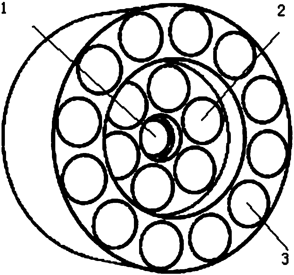
[0024] Such as figure 1 As shown, a reflective intensity modulation optical fiber sensor with unequal spacing dislocation compensating structure, including a sending optical fiber, two receiving optical fibers, the two receiving optical fibers are placed on the same side of the emitting optical fiber, and the three optical fibers are placed between two by two. Arranged at the same distance c.

[0025] The three optical fibers are not flush at the end faces of the fibers. A set of single fiber pairs is formed by the misalignment a of the sending fiber and one of the receiving fibers 2 at the end face of the fiber as a reference optical path. The receiving fiber 2 and the other receiving fiber 3 are on the end face of the fiber. The misalignment b is formed, and the sending optical fiber and the receiving optical fiber 3 form another group of single optical fiber pairs as the measuring optical path. The above is the improved unequal-pitch equal-core dislocation compensation str...


PUM


Abstract

The invention provides a reflective intensity modulation (RIM) optical fiber sensor unequally spaced misalignment type compensation structure, which comprises a sending optical fiber and two layers ofreceiving optical fiber groups. The structure of the invention is characterized in that the sending optical fiber and receiving optical fibers of each layer of receiving optical fiber group are arranged at an equal distance and not in the same plane; the end face of the sending optical fiber forms a misalignment quantity with the end face of the first layer of the receiving optical fiber group; the sending optical fiber and the first layer of the receiving optical fiber group constitute a reference light path; the end face of the first layer of receiving optical fiber group and the second layer of receiving optical fiber group form a misalignment quantity at the end face, and the sending optical fiber and the second layer of receiving optical fiber group constitute a measurement light path; and the sending optical fiber transmits a light source to a measured surface, and the light source is received by the two layers of receiving optical fiber groups after being reflected and is transmitted to a photoelectric detector which converts the light source into an electrical signal to be output. The optical fiber sensor compensation structure of the invention is an unequally spaced misalignment type and, combined with a two-circle coaxial probe structure, can effectively improve the linearity, sensitivity and range of measurement and eliminate measurement dead zones.

Description

technical field [0001] The invention belongs to the technical field of optical fiber sensing, and in particular relates to a reflection type intensity modulation type optical fiber sensor with unequal distance dislocation compensating structure. Background technique [0002] Optical fiber sensor is a new type of sensor developed rapidly in the 1970s. In recent decades, with the continuous development of fiber optic technology, fiber optic sensor technology has matured in a variety of non-contact measurement systems. Reflective intensity modulation (RIM) fiber optic sensors are widely used in Surface topography measurement. [0003] Since the RIM fiber optic sensor measures the topography of the measured surface through the change of light intensity, it must be affected by the fluctuation of the power of the light source. In addition, the reflectivity of the reflective surface is different, and the transmission loss of the optical fiber will cause a certain error to the mea...

Claims


Application Information

Patent Timeline
Patent Type & Authority Applications(China)
IPC IPC(8): G01B11/24
CPCG01B11/24
Inventor 杨瑞峰郭晨霞盖婷
Owner ZHONGBEI UNIV
Why Eureka
Try Eureka