A Bandgap Reference Circuit Without Operation Amplifier
A reference circuit, no op amp technology, applied in the direction of adjusting electrical variables, instruments, control/regulating systems, etc., can solve the problem of difficult to obtain a low temperature coefficient reference voltage, the performance of the operational amplifier A is reduced, and the accuracy of the reference voltage is affected. Achieve the effect of simple structure, reduced temperature coefficient and simplified circuit structure
- Summary
- Abstract
- Description
- Claims
- Application Information
AI Technical Summary
Problems solved by technology
Method used
Image
Examples
Embodiment 1
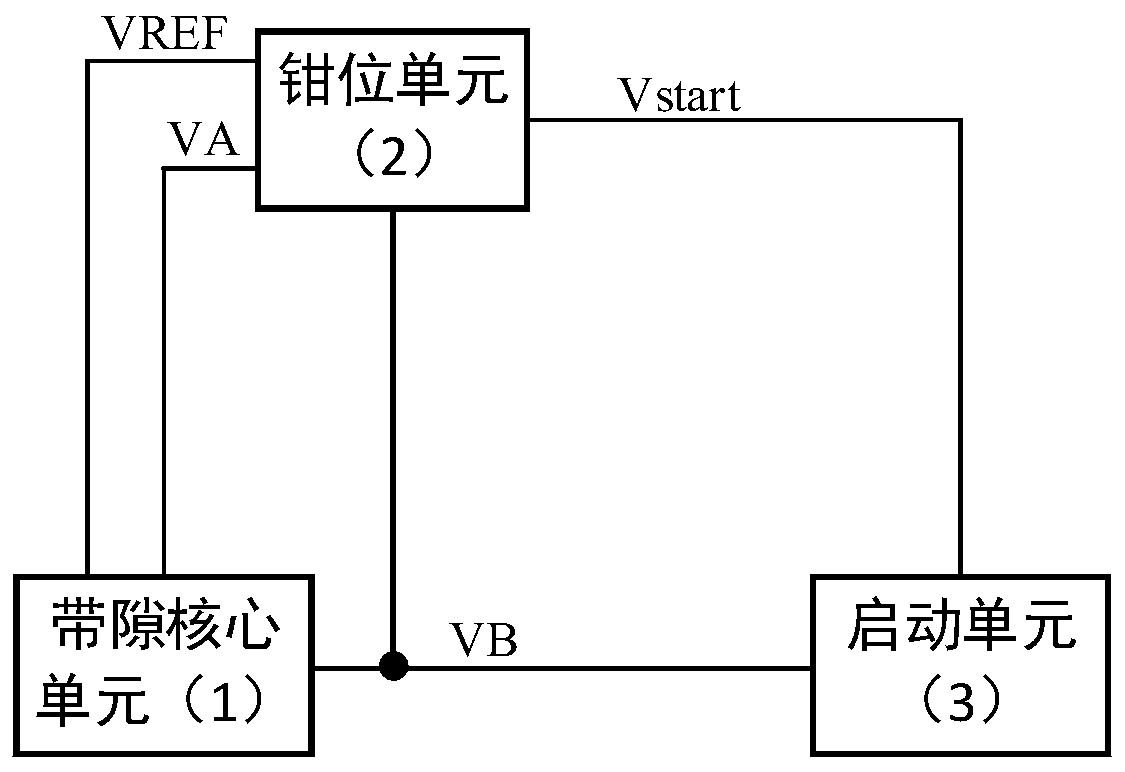
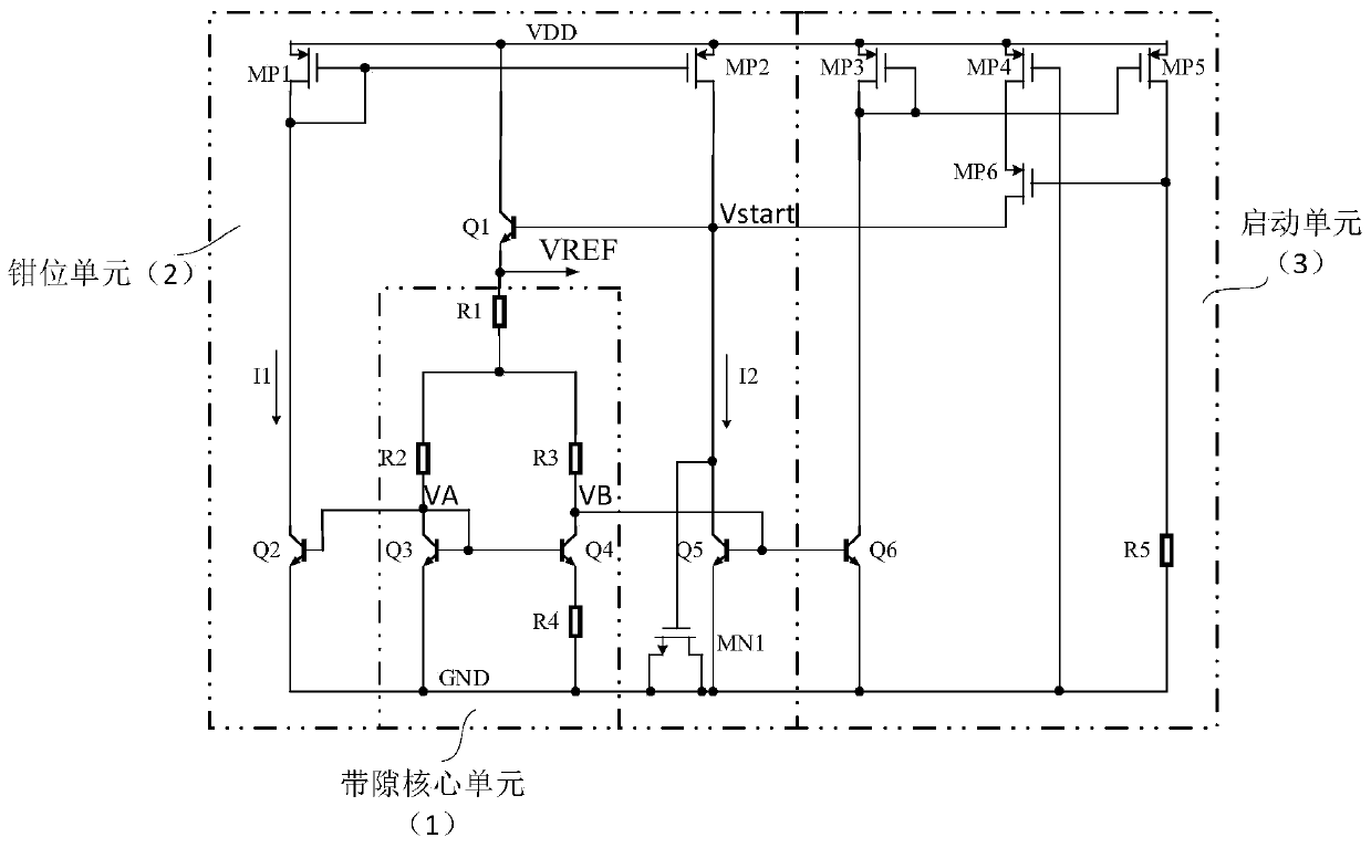
[0028] refer to figure 2 , the present invention includes: a bandgap core unit 1, a clamp unit 2 and a start unit 3; wherein the bandgap core unit 1 is provided with three output terminals, and its first output terminal outputs a clamp voltage VB; its second output terminal outputs a clamp voltage Bit voltage VA; its third output terminal outputs zero temperature coefficient reference voltage VREF. The clamping unit 2 is provided with three input terminals and one output terminal; its first input terminal is connected to the clamping voltage VA, its second input terminal is connected to the clamping voltage VB, and its third input terminal is connected to the start signal Vstart; its output terminal is connected to The zero temperature coefficient reference voltage VREF constitutes a negative feedback loop. The starting unit 3 is provided with an input terminal and an output terminal, the input terminal is connected to the clamp voltage VB; the output terminal outputs the st...
Embodiment 2
[0050] The bandgap core unit 1 and the clamp unit 2 of the present invention are the same as those in the first embodiment.
[0051] The above starting unit 3 includes a third PMOS transistor MP3, a fourth PMOS transistor MP4, a fifth PMOS transistor MP5, a sixth PMOS transistor MP6, a sixth NPN transistor Q6 and a fifth resistor R5; wherein: the third PMOS transistor MP3 and the fifth resistor R5 PMOS transistor MP5, its gate is connected to form a current mirror structure, and its source is connected to the power supply voltage VDD; the drain of the third PMOS transistor MP3 is connected to its own gate and connected to the collector of the sixth NPN transistor Q6; The drain of the fifth PMOS transistor MP5 is connected to GND through the fifth resistor R5; the emitter of the sixth NPN transistor Q6 is connected to GND, and its base is connected to the clamp voltage VB as the input terminal of the startup unit 3; the fourth PMOS transistor MP4 is connected to the gate of the...
PUM
 Abstract
Description
Claims
Application Information
 - R&D
- Intellectual Property
- Life Sciences
- Materials
- Tech Scout
- Unparalleled Data Quality
- Higher Quality Content
- 60% Fewer Hallucinations
Browse by: Latest US Patents, China's latest patents, Technical Efficacy Thesaurus, Application Domain, Technology Topic, Popular Technical Reports.
© 2025 PatSnap. All rights reserved.Legal|Privacy policy|Modern Slavery Act Transparency Statement|Sitemap|About US| Contact US: help@patsnap.com


