Compact rectangular TE10-circular waveguide TM01 mode conversion device

A TE10-, rectangular waveguide technology, applied to waveguide devices, electrical components, circuits, etc., can solve the problems of complex overall structure, limited practical application, narrow working frequency band, etc., and achieve firm connection, reduced dielectric loss, and high conversion efficiency high effect

Active Publication Date: 2018-05-15
UNIV OF ELECTRONICS SCI & TECH OF CHINA
View PDF2 Cites 8 Cited by
  • Summary
  • Abstract
  • Description
  • Claims
  • Application Information

AI Technical Summary

Problems solved by technology

conventionally designed TM 01 The working frequency band of the mode converter is narrow, the relative bandwidth is about 10%, and the overall structure is complex, which requires a dielectric support design, and the device size is large; there are improved structures such as those designed by Abdelwahed Tribak et al. in "ULTRA-BROADBAND HIGH EFFICIENCY MODE CONVERTER" The mode converter adopts the stepped coaxial inner conductor and the stepped rectangular-coaxial mode ma...

Method used


Image

  • Compact rectangular TE10-circular waveguide TM01 mode conversion device
  • Compact rectangular TE10-circular waveguide TM01 mode conversion device
  • Compact rectangular TE10-circular waveguide TM01 mode conversion device

Examples


Embodiment Construction

[0023] In order to make the technical solutions and advantages of the present invention clearer, the present invention will be further described in detail below in conjunction with specific embodiments and with reference to the accompanying drawings.

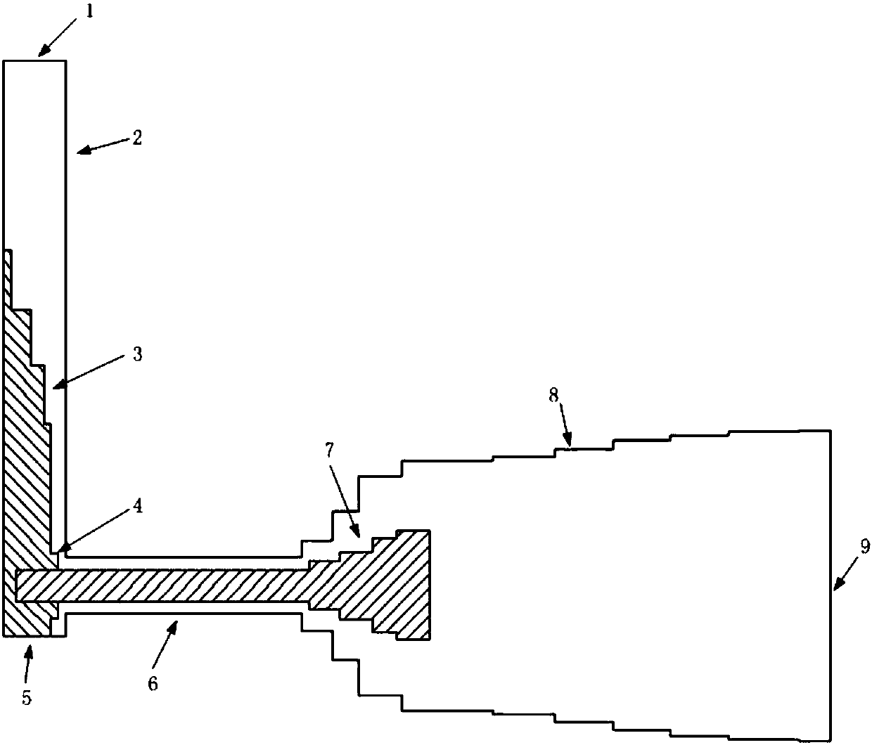
[0024] The cross-sectional structure of the embodiment of the present invention is as figure 1 As shown, including X-band standard BJ100 rectangular waveguide (waveguide size: wide side length 22.86mm, narrow side length 10.16mm), coaxial waveguide, stepped coaxial waveguide and stepped circular waveguide.

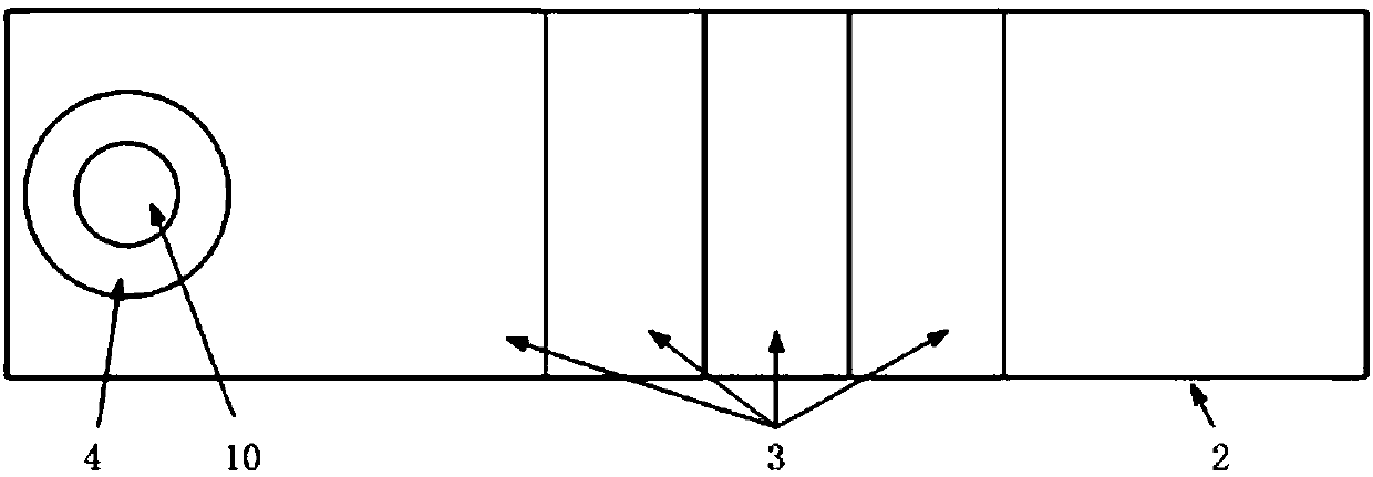
[0025] The standard rectangular waveguide is used to transmit X-band TE 10 Fundamental mode, one section of the standard rectangular waveguide uses a flange to connect with the signal source as the signal input end, and the other end is the short-circuit surface.

[0026] The rectangular waveguide is provided with a 4-stage metal ladder impedance matching structure with increasing length, and the step width is the same as t...


PUM


Abstract

The invention discloses a compact rectangular TE10-circular waveguide TM01 mode conversion device, and belongs to the technical field of microwave millimeter waves. The device comprises a rectangularwaveguide, a coaxial waveguide, a stepped coaxial waveguide and a stepped circular waveguide. A TE10 mode input from a standard rectangular waveguide is converted into a flat waveguide TE10 mode through a step. After that, the feed-in of the coaxial waveguide is realized through a side wall, and then a coaxial TEM mode is generated. The generated coaxial TEM mode is inputted into the subsequentlyconnected stepped coaxial waveguide. After entering the stepped coaxial waveguide, the TEM mode is subjected to the step-by-step transition of the stepped coaxial waveguide. After that, a circular waveguide TM01 mode is excited at the tail end of the TEM mode. The stepped circular waveguide structure is adopted at the output end of the device. In this way, on the premise that the output purity ofthe TM01 is ensured, the outer diameter of the coaxial waveguide is transited to an output port in a step-by-step mode. As a result, the coaxial waveguide is matched with the output port. The device can realize the output of the TM01 mode with the mode purity thereof larger than 99.5% in the BJ 100 full-waveguide bandwidth. Moreover, the length of a rectangular waveguide section is smaller than 95mm and the length of a circular waveguide section is smaller than 90 mm. An intermediate conversion structure adopts a non-supporting coarse coaxial transition design, and the device is small in insertion loss.

Description

technical field [0001] The invention belongs to the field of microwave and millimeter wave technology, in particular to an X-band rectangular waveguide TE 10 Mode-Circular Waveguide TM01 high-purity mode conversion device, especially suitable for TM 01 Pattern exciter applications. Background technique [0002] In the application of high-power microwave devices, connection problems between different devices and different interfaces are very common. When the mode of the required waveform is different from that of the existing waveform, a mode converter is required for transition connection. Mode conversion is a broad concept, theoretically it includes all devices capable of mode conversion. For most high-power microwave sources, such as relativistic Cherenkov devices, gyrotron devices, virtual cathode oscillators, etc., the working mode is generally a circular waveguide symmetric phantom (TE 0n 、TM 0n ) or advanced side corridor mode (TE mn , m >> 1, n ~ 1, 2). So...

Claims


Application Information

Patent Timeline
IPC IPC(8): H01P1/16
CPCH01P1/16
Inventor 汪海洋金磊
Owner UNIV OF ELECTRONICS SCI & TECH OF CHINA
Why Eureka
Try Eureka