High-safety braking energy recovery method for electric vehicle

A braking energy recovery and electric vehicle technology, applied in electric vehicles, electric braking systems, brakes, etc., can solve the problem of insufficient energy loss and collection, and achieve a scientific, effective and safe braking strategy High performance, with optimized effect

Inactive Publication Date: 2018-05-18
NANCHANG INST OF TECH
View PDF6 Cites 17 Cited by
  • Summary
  • Abstract
  • Description
  • Claims
  • Application Information

AI Technical Summary

Problems solved by technology

[0004] Although the research on automobile braking energy recovery system has made great progress in today's world, there are still some aspects that need to be solved or improved, such as: 1) Energy recovery efficiency
The braking energy recovery process is affected by various factors, so the collection of energy loss cannot be fully absorbed. Therefore, it is necessary to consider the issue of improving the efficiency of energy recovery to maximize
2) Vehicle brake safety issues
However, as far as the current situation is concerned, the above two problems have not been comprehensively and ideally resolved.

Method used


Image

  • High-safety braking energy recovery method for electric vehicle
  • High-safety braking energy recovery method for electric vehicle
  • High-safety braking energy recovery method for electric vehicle

Examples


Embodiment 1

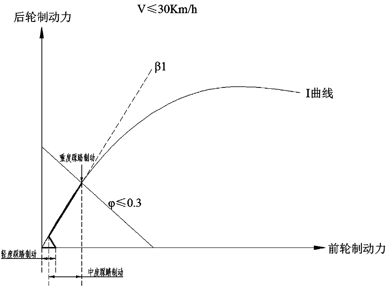
[0035] When the road surface adhesion coefficient φ≤0.3 and the vehicle speed v≤30km / h, the driver depresses the brake pedal slightly, the hydraulic brake system does not work, the front clutch is closed, the front axle motor rotates to generate power, and at the same time provides braking torque, and the power generated The electric energy flows into the battery management system through the current regulator, and then the battery management system is imported into the on-board lithium-ion battery, the rear clutch is disconnected, and the rear axle motor does not participate in braking; when the driver moderately steps on the brake pedal, the brake pedal The pressure sensor at the position transmits the signal to the vehicle controller, which is pre-set with the ideal front and rear wheel braking force distribution curve under the vehicle's no-load state, and the road surface recognition module transmits the adhesion coefficient value of the road surface in real time In the ve...

Embodiment 2

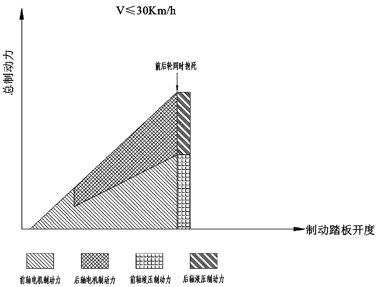
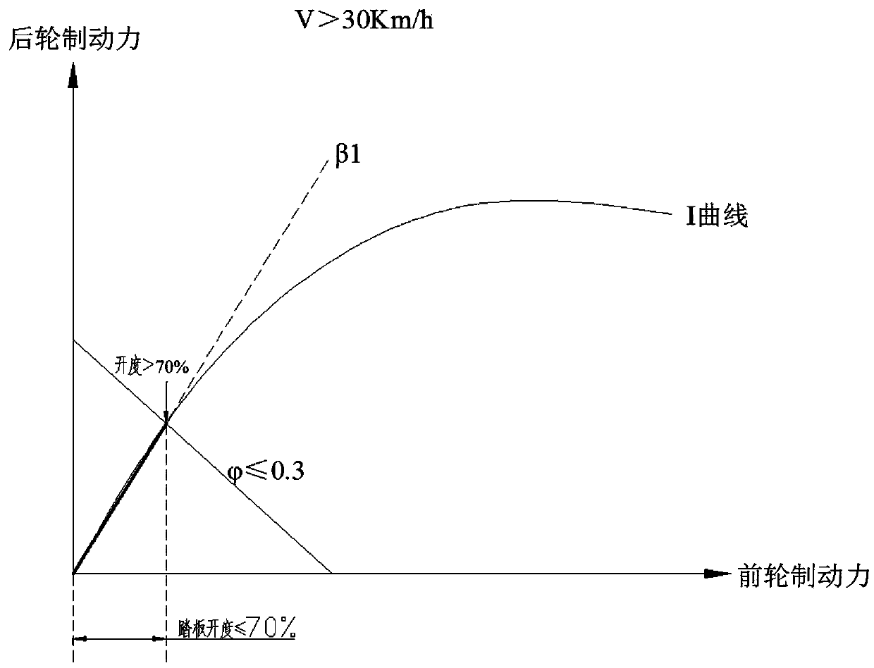
[0037] When the road surface adhesion coefficient φ≤0.3, the vehicle speed v>30km / h, and the opening of the driver’s brake pedal is ≤70% of the total opening, the vehicle controller closes the front clutch and the rear clutch at the same time, and outputs instructions to adjust Two current regulators, so that the ratio of the braking force of the front axle motor to the rear axle motor is β 1 , when the driver steps on the brake pedal and the opening is greater than 70% of the total opening, the front clutch and the rear clutch are disconnected, and the vehicle controller activates the hydraulic braking system to lock the front and rear wheels simultaneously. The braking force distribution curves of the front and rear axles and the total braking force-brake pedal opening curve are as follows: image 3 and Figure 4 shown.

Embodiment 3

[0039] When the road surface adhesion coefficient is 0.32 After being distributed to the front and rear axles, whether they are both less than the maximum braking force of the front axle motor and the rear axle motor, if less, then close the front clutch and rear clutch at the same time, adjust the two current regulators, and the vehicle controller according to the adhesion coefficient and the vehicle The ideal front and rear wheel braking force distribution curve under no-load conditions determines the ratio of the rear wheel braking force to the front wheel braking force β 2 , according to β 2 Distribute the braking force of the front axle motor and the rear axle motor to recover energy while maintaining the stability of the car. If the braking force corresponding to the brake pedal opening is according to β 2 After being distributed to the front and rear axles, one or both of them are greater than the maximum braking force of the front axle motor or the rear axle motor, the...


PUM


Abstract

The invention discloses a high-safety braking energy recovery system for an electric vehicle. The high-safety braking energy recovery system for the electric vehicle includes a motor braking system, atraditional hydraulic braking system and an auxiliary braking system. Based on the braking energy recovery system, a braking energy recovery method for electric vehicle is designed. According to a road attachment coefficient, a vehicle speed and an open degree of a braking pedal, the braking force of the front and rear wheels is allocated. Compared with the prior art, two front and back braking motors are used, and the distribution of feedback braking force can be regulated by a current regulator. The maximum braking energy recovery rate is guaranteed, at the same time, the stability of an automobile braking process is maintained, the vehicle side skidding or deviating are avoided, and the safety performance of the braking energy recovery is high.

Description

technical field [0001] The invention belongs to the technical field of new energy vehicles, and in particular relates to a high-safety electric vehicle braking energy recovery method. Background technique [0002] Due to its advantages such as relatively small environmental pollution, low noise, high efficiency, simple structure, convenient maintenance and durability, pure electric vehicles have attracted widespread attention from various countries, and have also triggered a worldwide automotive revolution. . [0003] The electric vehicle braking energy recovery system refers to a system that converts part of the kinetic energy of the vehicle into electrical energy through a generator during the braking process of the vehicle and stores it, and provides all or part of the driving force for the vehicle when the vehicle is accelerated or started. During the braking process, the mechanical energy of the driving wheel is converted into electrical energy through an energy conver...

Claims


Application Information

Patent Timeline
Patent Type & Authority Applications(China)
IPC IPC(8): B60L7/10B60L15/20B60T8/171
CPCB60L7/10B60L15/20B60T8/171Y02T10/64Y02T10/72
Inventor 杨军平
Owner NANCHANG INST OF TECH
Why Eureka
Try Eureka