Transformer external type electrostatic coalescer

An electrostatic coalescence and transformer technology, applied in the direction of electricity/magnetic dehydration/emulsification, etc., can solve the problems of shortening settling time, unstable operation of equipment, crossing electric field, etc., to improve dehydration efficiency, increase coalescence effect, structure simple effect

Pending Publication Date: 2018-05-18
BEIJING INSTITUTE OF PETROCHEMICAL TECHNOLOGY
View PDF7 Cites 1 Cited by
  • Summary
  • Abstract
  • Description
  • Claims
  • Application Information

AI Technical Summary

Problems solved by technology

This scheme shortens the settling time and improves the separation efficiency. However, the internal fluid flow state of conventional electric dehydrators is laminar flow. When the water content in crude oil is low, the distance between water particles is relatively large, and it takes a long time to complete effective coalescence. This leads to long settling time and bulky equipment; when the water content in crude oil is high, the distance between water particles is small, and cross-electric field phenomenon is prone to occur. Corrosion and short circuit are very easy to occur, and the operation of the equipment is unstable; and the electrodes used on the downstream side of the electric dehydrator and the three-phase separator are all metal plates, and a uniform electric field is formed between the electrodes, which is not conducive to the dehydration of low-water crude oil. Coalescer and coalescing module electrodes adopt tubular electrodes, but the fluid flow direction is along the radial direction of the electrodes, and the coalesced water particles collide with the electrodes, which are easy to break again

Method used


Image

  • Transformer external type electrostatic coalescer
  • Transformer external type electrostatic coalescer
  • Transformer external type electrostatic coalescer

Examples


Embodiment Construction

[0020] The technical solutions in the embodiments of the present invention will be clearly and completely described below in conjunction with the accompanying drawings in the embodiments of the present invention. Obviously, the described embodiments are only some of the embodiments of the present invention, not all of them. Based on the embodiments of the present invention, all other embodiments obtained by persons of ordinary skill in the art without making creative efforts belong to the protection scope of the present invention.

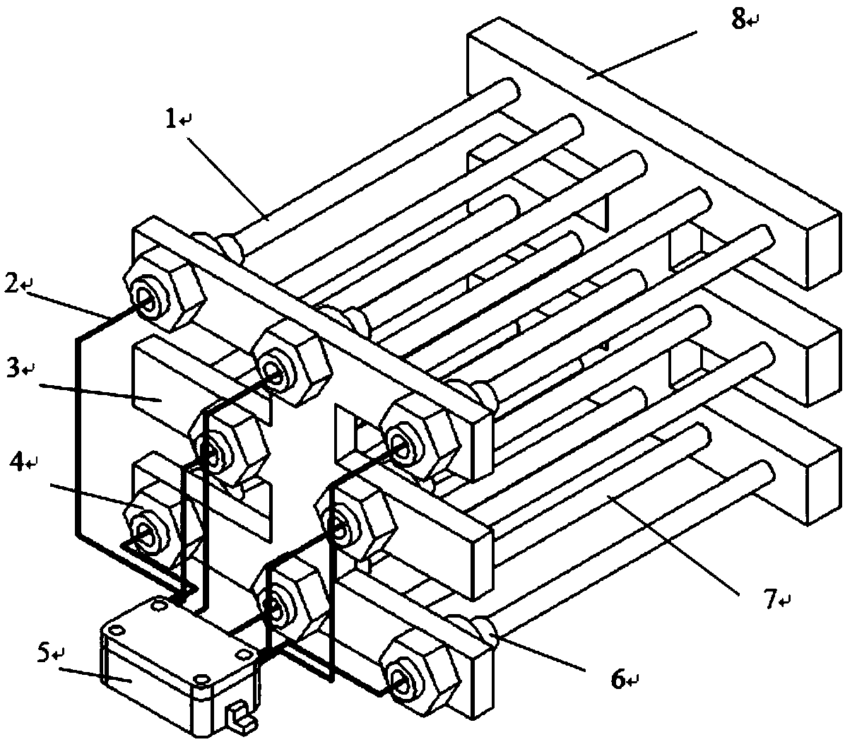
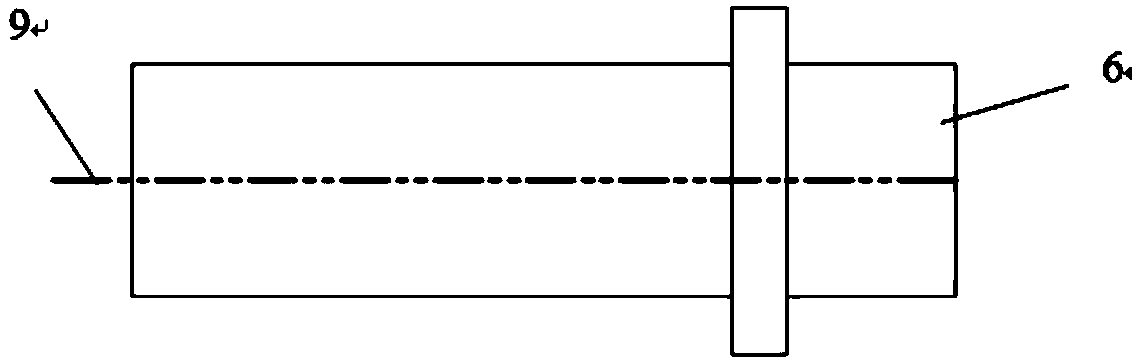
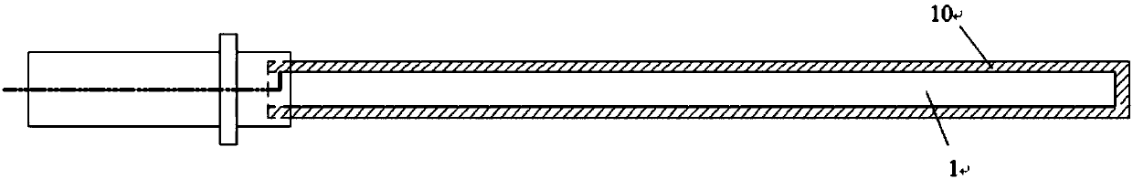
[0021] Embodiments of the present invention will be further described in detail below in conjunction with the accompanying drawings, as figure 1 Shown is a schematic structural diagram of an external transformer electrostatic coalescer provided by an embodiment of the present invention, the electrostatic coalescer includes a high-voltage electrode assembly 1, a metal hose 2, a first metal frame support 3, a fixing nut 4, a high-voltage branch Junct...


PUM


Abstract

The invention provides a transformer external type electrostatic coalescer. The transformer external type electrostatic coalescer comprises a high-voltage electrode assembly, a metal hose, a first metal frame bracket, a fixed nut, a high-voltage junction box, an insulating connecting piece, a low-voltage electrode assembly and a second metal frame bracket; each of the high-voltage electrode assembly and the low-voltage electrode assembly consists of a plurality of electrode tubes; the electrode tubes are arranged linearly; the adjacent electrodes are connected with high voltage and the groundcorrespondingly; the high-voltage electrode assembly is connected with the insulating connecting piece, the insulating connecting piece is connected with the metal hose, and the metal hose is connected with the high-voltage junction box; the high-voltage junction box is connected with an external transformer through a high-voltage cable; the external transformer is positioned at the top of an electric dehydration area and on the outer side of a three-phase separator; and the low-voltage electrode assembly is welded with the second metal frame bracket and grounded. The electrostatic coalesce issimple in structure and convenient to maintain, a non-uniform electric field is formed between the electrodes, the coalescence effect of water granules is improved and the dehydration efficiency is improved.

Description

technical field [0001] The invention relates to the technical field of crude oil dehydration equipment, in particular to an electrostatic coalescer with an external transformer. Background technique [0002] Oil and gas gathering and transportation is an important link in crude oil production, and dehydration of crude oil is a key step. At present, the dehydration method of produced fluid mainly adopts the process of three-phase separator + electric dehydrator. As the exploitation of onshore oilfields enters the middle and later stages, the water content of produced fluid gradually increases, and the oil at the oil outlet of the three-phase separator The phenomenon that the moisture content in the medium does not meet the standard often occurs. [0003] The basic principle of the electric dehydrator in the prior art is that crude oil enters the electric dehydrator from the bottom and moves from bottom to top. The water particles in it are coalesced and the particle size inc...

Claims


Application Information

Patent Timeline
Patent Type & Authority Applications(China)
IPC IPC(8): C10G33/02
CPCC10G33/02
Inventor 张宝生尹永明宋国治
Owner BEIJING INSTITUTE OF PETROCHEMICAL TECHNOLOGY
Why Eureka
Try Eureka