
3D rapid high-resolution tunnel construction advanced intelligent forecasting method

A tunnel construction, high-resolution technology, applied in the field of tunnel construction forecasting, can solve the problems of difficult conversion wave, strong multi-solution of prediction results, disasters, etc., and achieve simple and fast signal processing, high precision of processing results, and strong reduction of multi-solution Effect

Inactive Publication Date: 2018-05-18
钱荣毅
View PDF5 Cites 3 Cited by
  • Summary
  • Abstract
  • Description
  • Claims
  • Application Information

AI Technical Summary

Problems solved by technology

[0004] Due to the limited construction space in the tunnel, TSP, TRT and other technologies adopt the method of arranging the observation system on the tunnel wall. For the geological body in front of the tunnel face, the real three-dimensional observation cannot be achieved, and it is difficult to fully and accurately obtain The wave velocity information from the surrounding rock in front of the tunnel face and the reflection information of bad abnormal bodies; secondly, due to the limitation of the observation method, the seismic wave signals obtained by TSP, TRT and other technologies are more complex than the seismic phases observed on the land surface, and it is necessary to identify surface waves , longitudinal waves, shear waves, and converted waves are difficult, which makes the processing of seismic wave signals difficult and takes a long time, which seriously affects the construction progress, and the prediction results of the geological bodies in front of the tunnel face are more ambiguous and less accurate At the same time, the existing advance prediction technology based on seismic waves mostly uses the data obtained at a single time as the prediction data, so as to predict the geological structure in front of the tunnel face, without connecting the actual physical properties of the surrounding rock (such as rock porosity , surrounding rock density, etc.) with the changes of the construction progress, the dynamic change information of the geological structure in front of the tunnel face cannot be obtained; thirdly, because TSP, TST and other technologies need to perform seismic source excitation and signal reception on the tunnel wall, the construction process It has caused an impact and increased the construction cost, and its source excitation method is dangerous to a certain extent, which may easily cause damage to the tunnel wall and cause unnecessary disasters

Method used


Image

  • 3D rapid high-resolution tunnel construction advanced intelligent forecasting method
  • 3D rapid high-resolution tunnel construction advanced intelligent forecasting method
  • 3D rapid high-resolution tunnel construction advanced intelligent forecasting method

Examples


Embodiment 1

[0075] Take the case where there is an inclined fault in front of the tunnel face as an example, such as Figure 3a shown. See Table 1 for related parameter settings.

[0076] Table 1

[0077]

[0078] The forecasting method specifically includes the following steps:

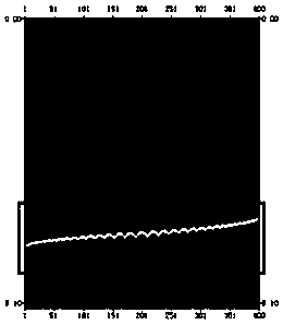
[0079] (1) According to the arrangement of the observation system, the single-shot record is obtained by excitation and reception on the face, such as Figure 4a-4b shown.

[0080] (2) Obtain samples of the face rock and the surrounding rock of the completed tunnel, measure the wave velocity, density and hardness of the rock, and measure the distribution of cracks in the sample rock.

[0081] (3) The acquired single-shot records are processed by the extraction channel set, and according to the acquired longitudinal and shear wave velocities of the tunnel face rock, according to formula 1, superposition processing is carried out.

[0082]

[0083] In the formula, t(x m ,h) is the two-way travel time ...

Embodiment 2

[0093] Take the situation where there is a lone stone in front of the palm as an example, such as Figure 3b shown. See Table 2 for related parameter settings.

[0094] Table 2

[0095]

[0096] The forecasting method specifically includes the following steps:

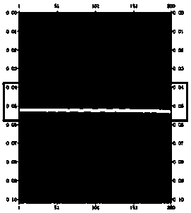
[0097] (1) According to the arrangement of the observation system, the single-shot record is obtained by excitation and reception on the face, such as Figure 4c-4d shown.

[0098] (2) Obtain samples of the face rock and the surrounding rock of the completed tunnel, measure the wave velocity, density and hardness of the rock, and measure the distribution of cracks in the sample rock.

[0099] (3) The acquired single-shot records are processed by the extraction channel set, and according to the acquired longitudinal and shear wave velocities of the tunnel face rock, according to formula 1, superposition processing is carried out. Overlay results such as Figure 5b shown.

[0100] (4) Extract the seismic attri...


PUM


Abstract

The invention discloses a 3D rapid high-resolution tunnel construction advanced intelligent forecasting method. An observation method that excites seismic waves on the tunnel face and receives multiple coverage imaging of reflection wave signals on the tunnel face in a 3D mode is employed, high-sensitivity broadband sensors can be quickly combined to arrange a 3D reception system based on the shape and a construction mode of the tunnel face, a broadband seismic source is further utilized at the tunnel face to carry out rapid and regular automatic excitation without causing damage to the tunnelface, construction is simple, repeatability is strong, and the risk is low; and secondly, excitation and data acquisition at different construction processes of the tunnel are carried out, in combination with physical properties of surrounding rocks (such as surrounding rock density, the Poisson's ratio, etc.) acquired during tunnel construction, a tunnel database is established, through comparing the data at different times, high-resolution detection of the geological information in front of the tunnel face can be carried out, and geological disasters within 500 meters ahead of the tunnel face are detected.

Description

technical field [0001] The invention relates to the field of tunnel engineering, in particular to a method for forecasting tunnel construction. Background technique [0002] In mountainous countries, as a concealed project with high construction risk, tunnel has the advantages of less impact on the environment, less land occupation and short travel distance, and has received more and more attention. However, in the tunnel excavation process, various unfavorable geological areas (faults, broken zones, collapsed columns, caves, groundwater, etc.) are often encountered, which pose a great threat to construction safety due to their concealment and suddenness. It also has a great impact on the construction progress. In order to reduce the risk during tunnel excavation and reduce the damage to personnel and mechanical equipment caused by adverse geological disasters, it has important practical significance and considerable economic benefits to use advanced geological prediction t...

Claims


Application Information

Patent Timeline
IPC IPC(8): G01V1/28G01V1/24
CPCG01V1/247G01V1/28
Inventor 钱荣毅宋翱钱志强宋斌
Owner 钱荣毅
Learn More