Feed gas recovery method and device
A recovery method and recovery device technology, applied in separation methods, chemical instruments and methods, gas treatment, etc., can solve the problems of difficult control of the content of flammable and explosive components, and reduce the concentration of flammable and explosive components, process The effect of simple and reliable process and less equipment
- Summary
- Abstract
- Description
- Claims
- Application Information
AI Technical Summary
Problems solved by technology
Method used
Image
Examples
Embodiment 1
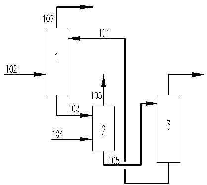
[0035] Embodiment 1 provides a general structural block diagram and a method flow chart of the present invention. Such as figure 1 As shown, a raw material gas recovery device includes an absorption module 1 and a recovery module 2, the absorption module 1 is an absorption tower, the recovery module 2 is a recovery tower, and the mass transfer equipment-recovery tower is preferably a plate tower, a packed tower and other towers The upper part of the absorption module 1 is provided with a lean liquid inlet, and the lean liquid also includes semi-poor liquid. The lean liquid 101 and the raw material gas 102 are fully contacted countercurrently in the absorption tower, and the lean liquid 101 absorbs the raw material gas 102 to obtain the rich liquid 103. The absorption module 1 and the recovery module 2 are connected, and the obtained rich liquid 103 enters the recovery module 2 from the absorption module 1. The rich liquid inlet is located on the upper part of the recovery mod...
Embodiment 2
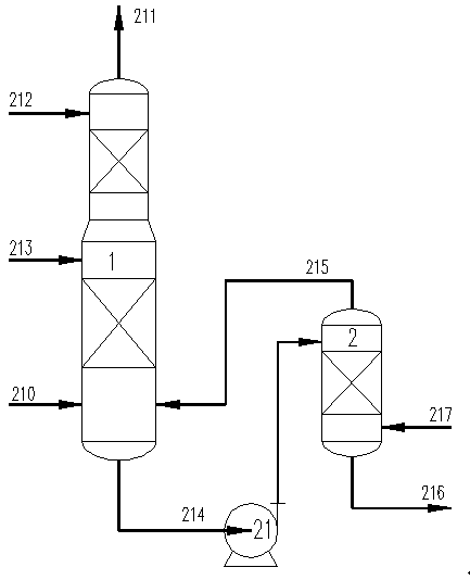
[0037] Taking synthetic ammonia from coke oven gas as an example, the raw material gas treatment capacity of the decarbonization section is 37400Nm 3 / h (dry basis), the annual operating time is 8000h, the volume concentration of the main components of the raw gas is: 72.8% hydrogen, 24.8% carbon dioxide, 2.0% nitrogen, 0.2% methane, 0.2% carbon monoxide; the pressure is : 2.95MPa(A); temperature: 50°C. The operating pressure of the decarburization absorption tower is 2.9MPa(A), the lean liquid 212 uses 45% MDEA, the semi-lean liquid 213 uses 5% piperazine aqueous solution, the temperature of the semi-lean liquid is 69°C, and the feed rate is 306t / h. The liquid temperature is 55°C, the feed rate is 101t / h, the amount of rich liquid at the bottom of absorption module 1 is 471t / h, and the amount of hydrogen dissolved in the rich liquid is 635Nm 3 / h.
[0038] Such as figure 2 As shown, a raw material gas recovery device includes an absorption module 1 and a recovery module 2...
Embodiment 5
[0053] Such as Figure 7 As shown, a raw material gas recovery device includes an absorption module 1 and a recovery module 2. The absorption module 1 is an absorption tower, and the absorption tower includes an upper decarburization section, a middle section, and a lower desulfurization section. The upper part of the decarburization section is set There are lean liquid inlet and semi-lean liquid inlet, lean liquid 712 and semi-lean liquid 713 respectively enter the decarburization section from the lean liquid inlet and semi-lean liquid inlet; the decarburization section is provided with a middle section cooler 75 and a desulfurization section feed cooler 74; the lower part of the desulfurization section is provided with a raw material gas inlet, and the raw material gas 710 enters the desulfurization section from the raw material gas inlet; the lean liquid 712 and semi-lean liquid 713 entering the absorption module 1 are fully contacted with the raw material gas 710 in counter...
PUM
 Abstract
Description
Claims
Application Information
 - R&D
- Intellectual Property
- Life Sciences
- Materials
- Tech Scout
- Unparalleled Data Quality
- Higher Quality Content
- 60% Fewer Hallucinations
Browse by: Latest US Patents, China's latest patents, Technical Efficacy Thesaurus, Application Domain, Technology Topic, Popular Technical Reports.
© 2025 PatSnap. All rights reserved.Legal|Privacy policy|Modern Slavery Act Transparency Statement|Sitemap|About US| Contact US: help@patsnap.com


