Al technical title is built by PatSnap Al team. It summarizes the technical point description of the patent document.
A kind of kiln and environmental protection technology, applied in the field of kiln, can solve the problems of insufficient use of heat, unfavorable high temperature sintering, high energy consumption, etc.
Inactive Publication Date: 2018-05-22
长沙市西欧电子科技有限公司
View PDF5 Cites 0 Cited by
Summary
Abstract
Description
Claims
Application Information
AI Technical Summary
This helps you quickly interpret patents by identifying the three key elements:
Problems solved by technology
Method used
Benefits of technology
Problems solved by technology
The first type of flue gas requires an additional combustion source, which consumes a lot of energy, and the heat is not fully utilized
In addition, the existing environmentally friendly kilns are constructed in one piece, and the cost is high. Although the waste heat is used, the injection of low-temperature flue gas into the high-temperature furnace is not conducive to high-temperature sintering and affects the atmosphere.
The medium-temperature kiln is passively heated, and the high-temperature and low-temperature furnaces affect each other, which is not conducive to the control of the heating curve
When the kiln body products are broken or the kiln furniture is damaged, it is easy to cause accidents and it is inconvenient to maintain
Method used
Image
Click on the blue label to locate the original text in one second.
Reading with bidirectional positioning of images and text.
Examples
Embodiment 1
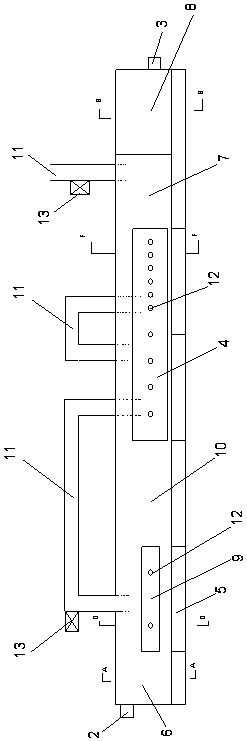
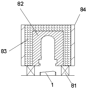
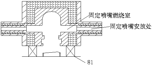
[0028] Such as Figure 1~4 As shown, an environment-friendly wax and deglue kiln includes a kiln body, a track 1 is set at the bottom of the kiln body, a kiln inlet 2 is set on the left side of the kiln body, and a kiln outlet 3 is set on the right side. The kiln body includes Combustion chamber 4, preheating zone 5, flue gas leakage prevention zone 6, cooling zone 7 and cooling flue gas leakage prevention zone 8, preheating zone 5 is provided with preheating combustion chamber 9, and flue gas leakage prevention zone 6 is located in the preheating combustion chamber The left side of 9 is connected with the preheating combustion chamber 9, the preheating zone 5 is located on the left side of the combustion chamber 4, the middle of the preheating zone 5 and the combustion chamber 4 is connected through the non-combustion chamber 10 of the furnace body, and the right side of the combustion chamber 4 is sequentially The cooling zone 7 and the cooling flue gas leakage prevention zo...
PUM
Abstract
The invention relates to kilns, and particularly discloses an environment-friendly wax and glue removing kiln. The environment-friendly wax and glue removing kiln comprises a kiln body. The kiln bodycomprises a combustion chamber, a preheating region, a flue gas leakage-roof region, a cooling region and a cooled flue gas leakage-roof region. The preheating region is provided with a preheating combustion chamber. The flue gas leakage-roof region is located at the left side of the preheating combustion chamber and is further connected with the preheating combustion chamber. The preheating region is located at the left side of the combustion chamber and is further connected with the combustion chamber through a furnace body non-combustion chamber. The right side of the combustion chamber issequentially connected with the cooling region and the cooled flue gas leakage-roof region. The preheating region is connected with the combustion chamber through a flue. The environment-friendly waxand glue removing kiln can achieve periodic propulsion and continuous production, the size of a hearth is small, and the temperature is constant and can be controlled conveniently.
Description
technical field [0001] The invention relates to a kiln, in particular discloses an environment-friendly wax and glue removal kiln. Background technique [0002] There are many kinds of special ceramics, among which zirconia and alumina have mature technology, a broad market and the largest market share. In the field of alumina and zirconia ceramic production, the molding methods mainly include: dry pressing molding, grouting molding, pouring molding, injection molding, tape casting, film rolling molding, static pressure molding, etc. Among them, dry pressing molding, grouting molding, and tape casting molding occupy an absolute position due to their mature technology and wide application range. However, the main pollution sources of the three molding processes are binders and plasticizers, among which binders mainly include: polyvinyl alcohol, methyl cellulose, polyvinyl alcohol, butyral, polyethylene glycol, carboxymethyl Cellulose, ethyl cellulose, carboxypropyl cellulos...
Claims
Application Information
Patent Timeline
Application Date:The date an application was filed.
Publication Date:The date a patent or application was officially published.
First Publication Date:The earliest publication date of a patent with the same application number.
Issue Date:Publication date of the patent grant document.
PCT Entry Date:The Entry date of PCT National Phase.
Estimated Expiry Date:The statutory expiry date of a patent right according to the Patent Law, and it is the longest term of protection that the patent right can achieve without the termination of the patent right due to other reasons(Term extension factor has been taken into account ).
Invalid Date:Actual expiry date is based on effective date or publication date of legal transaction data of invalid patent.