Supercharge Your Innovation With Domain-Expert AI Agents!

Earthquake model speed detection system

A velocity detection and modeling technology, applied in seismic surveying, seismology, teaching models, etc., can solve the problems of different test results, vibration signal conversion that cannot be smoothed, low-frequency signal interference of shaking table, etc., to achieve accurate measurement results and simple structure. , to ensure reproducible results

Active Publication Date: 2018-05-22
CHINA PETROLEUM & CHEM CORP +1
View PDF8 Cites 1 Cited by
  • Summary
  • Abstract
  • Description
  • Claims
  • Application Information

AI Technical Summary

Problems solved by technology

[0004] ①Because the amplitude-frequency characteristics of the commonly used wave transmitting and receiving devices are not flat enough at present, the wave transmitting device cannot send vibration output signals of equal amplitude at each frequency point, and the wave detecting device cannot achieve equal amplitude reception; that is, the wave transmitting device cannot The flat voltage driving signal is converted into a flat vibration driving signal, and the wave receiving device cannot convert the flat vibration signal into a flat voltage signal for collection and processing
The result of this is that the resonant frequency f obtained is not accurate enough
[0005] ② Poor repeatability
Since the propagation of the wave in the tested sample is related to the coupling between the wave transmitting and receiving device and the tested sample, different test results will be caused if the degree of compression is different.
[0006] ③ There are many manual interventions and the test efficiency is low. The test results are related to the habits and qualities of the experimenters
In addition, the vibrating table is susceptible to interference from external low-frequency signals transmitted from the ground.

Method used


Image

  • Earthquake model speed detection system
  • Earthquake model speed detection system

Examples


Embodiment Construction

[0022] The details of the present invention can be understood more clearly with reference to the accompanying drawings and the description of specific embodiments of the present invention. However, the specific embodiments of the present invention described here are only for the purpose of explaining the present invention, and should not be construed as limiting the present invention in any way. Under the teaching of the present invention, the skilled person can conceive any possible deformation based on the present invention, which should be considered as belonging to the scope of the present invention, and the present invention will be further described below in conjunction with the accompanying drawings.

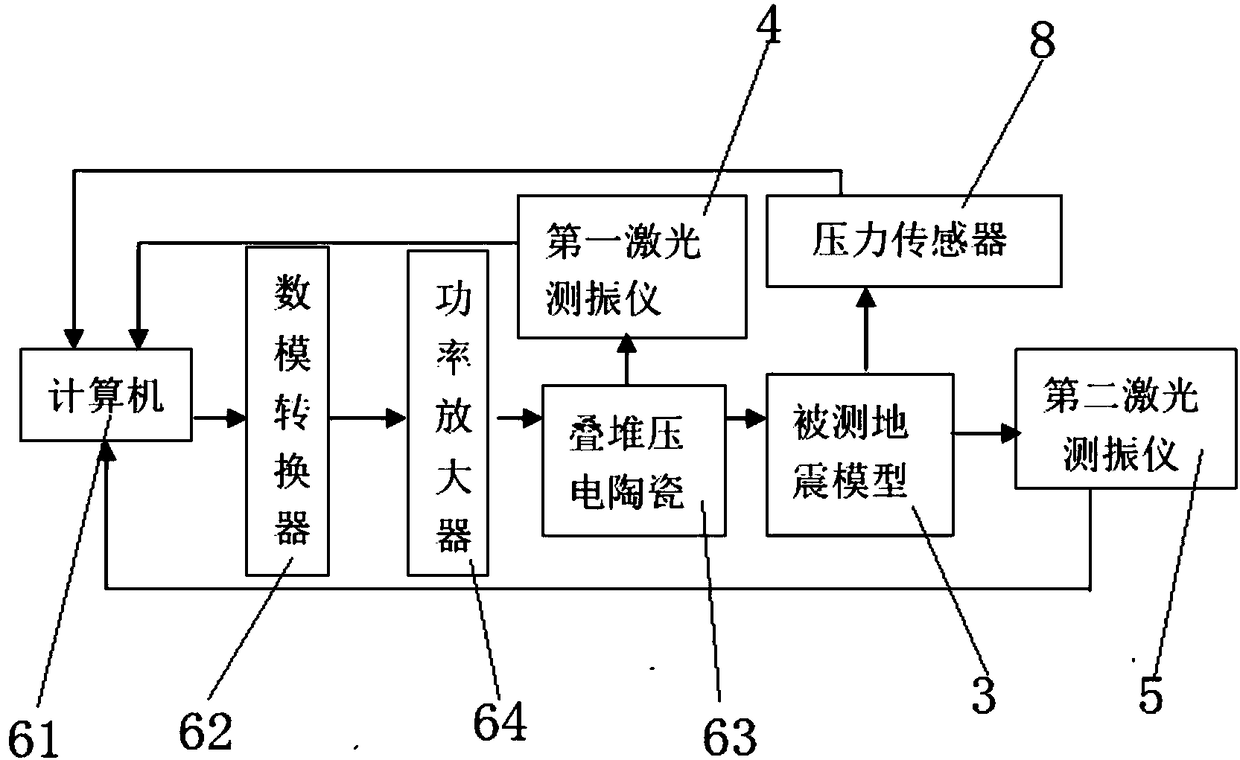
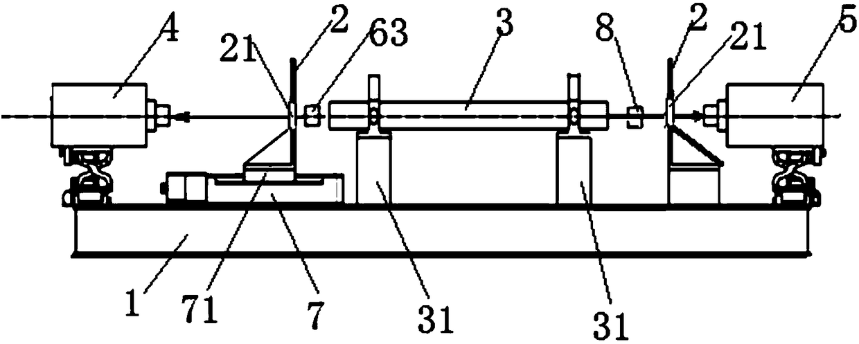
[0023] figure 1 and figure 2 They are respectively the composition block diagram of the seismic model velocity detection system and the structural schematic diagram of the seismic model velocity detection system of the present invention.

[0024] Such as figure 1 and ...


PUM


Abstract

The invention proposes an earthquake model speed detection system, and the system is disposed on a test bench. The system comprises two clamping plates, and at least one clamping plate can slide relative to the test bench. A to-be-detected earthquake model is clamped between two clamping plates, and the clamping plates are provided with through holes which are opposite to the earthquake model. Twoends of the earthquake model are respectively provided with a first laser vibration meter and a second laser vibration meter. A vibration signal transmitting analyzer is disposed between the first laser vibration meter and the earthquake model, and the vibration signal transmitting analyzer is electrically connected with the first and second laser vibration meters. The system provided by the invention can be used for accurately and quickly testing the speed of the earthquake model, can output constant amplitude vibration drive signals at all frequency points in the bandwidth range from 1hz to100khz, can achieve the broadband receiving of the vibration signals passing through the earthquake model, does not need manual intervention in an operation process, is high in accuracy of a measurement result and repeatability.

Description

technical field [0001] The invention relates to the technical field of geophysics, in particular to a detection system for seismic model velocity. Background technique [0002] The resonance method is an important method for measuring the velocity of elastic waves, which is based on the principle of standing waves, whose vibrations are similar to those in organ pipes. The measured sample contains an integer number of half-wavelengths of vibration, that is, the sample length L=n(λ / 2), where n is an integer, and λ is the wavelength of the standing wave, so the phase velocity of the wave v=λf=2Lf / n . [0003] The equipment needed to adopt this method is relatively simple, but the following problems exist when the laboratory adopts the device of this method for speed measurement: [0004] ①Because the amplitude-frequency characteristics of the commonly used wave transmitting and receiving devices are not flat enough at present, the wave transmitting device cannot send vibratio...

Claims


Application Information

Patent Timeline
Patent Type & Authority Applications(China)
IPC IPC(8): G01H5/00G01V1/00G09B23/40
CPCG09B23/40G01H5/00G01V1/01
Inventor 宗遐龄薛诗桂王辉明刘东方
Owner CHINA PETROLEUM & CHEM CORP
Features
  • R&D
  • Intellectual Property
  • Life Sciences
  • Materials
  • Tech Scout
  • Unparalleled Data Quality
  • Higher Quality Content
  • 60% Fewer Hallucinations
Learn More