Boiling bed reactor

A fluidized bed reactor and the technology of the reactor, which are applied in the fluidized bed field, can solve the problems of not too much catalyst dosage, low utilization rate of the reactor, and increased catalyst amount, etc., and achieve improved hydrogenation reaction effect, good separation effect, Avoid the effect of sticking

Active Publication Date: 2018-05-25
上海竣铭化工工程设计有限公司
View PDF6 Cites 4 Cited by
  • Summary
  • Abstract
  • Description
  • Claims
  • Application Information

AI Technical Summary

Problems solved by technology

[0004] There are currently two main types of ebullating hydrogenation technology, one is the oil phase circulation method, such as the ebullating bed process described in USRe25,770, the disadvantage of this process in practical application is: in order to maintain the liquid-solid separation effect, The amount of catalyst in the reactor should not be too much, and the utilization rate of the reactor is low. The utilization rate of the industrial ebullating bed reactor is generally only about 40%. The utilization rate generally refers to the percentage of the catalyst loading in the reactor volume (excluding the head space). The utilization rate of the reactor is generally above 90%; there is a large space in the reactor because the residence time of the liquid material is too long without catalytic conditions, there is no hydrogenation reaction in this part, and the material is easy to react and coke at high temperature
This effect has a significant impact on the separation effect of the existing three-phase separator, that is, when the catalyst loading increases, the resistance of the solid catalyst separated by the three-phase separator to settle back into the reactor increases, and is carried out of the reactor by the liquid material The chance of increasing the amount of catalyst taken out of the reactor will increase, which will affect the reaction effect

Method used


Image

  • Boiling bed reactor
  • Boiling bed reactor
  • Boiling bed reactor

Examples


Embodiment 1

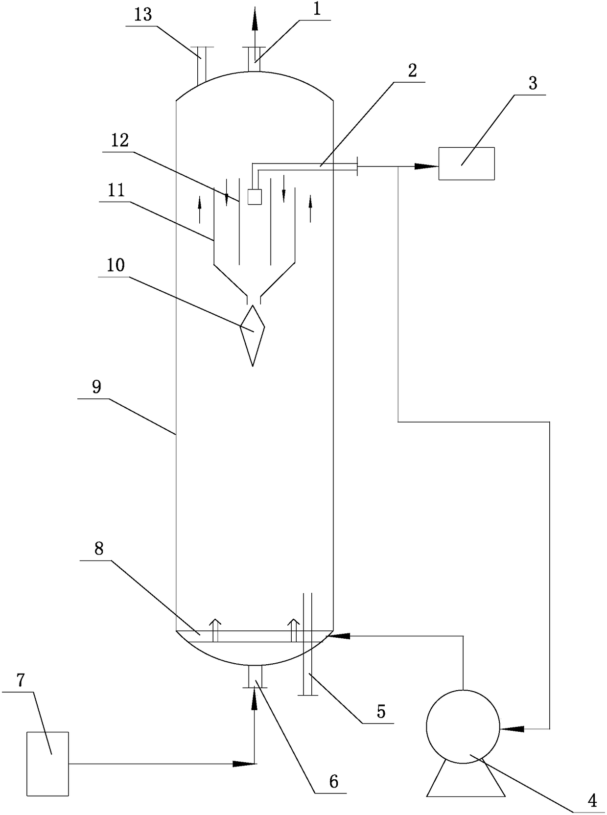
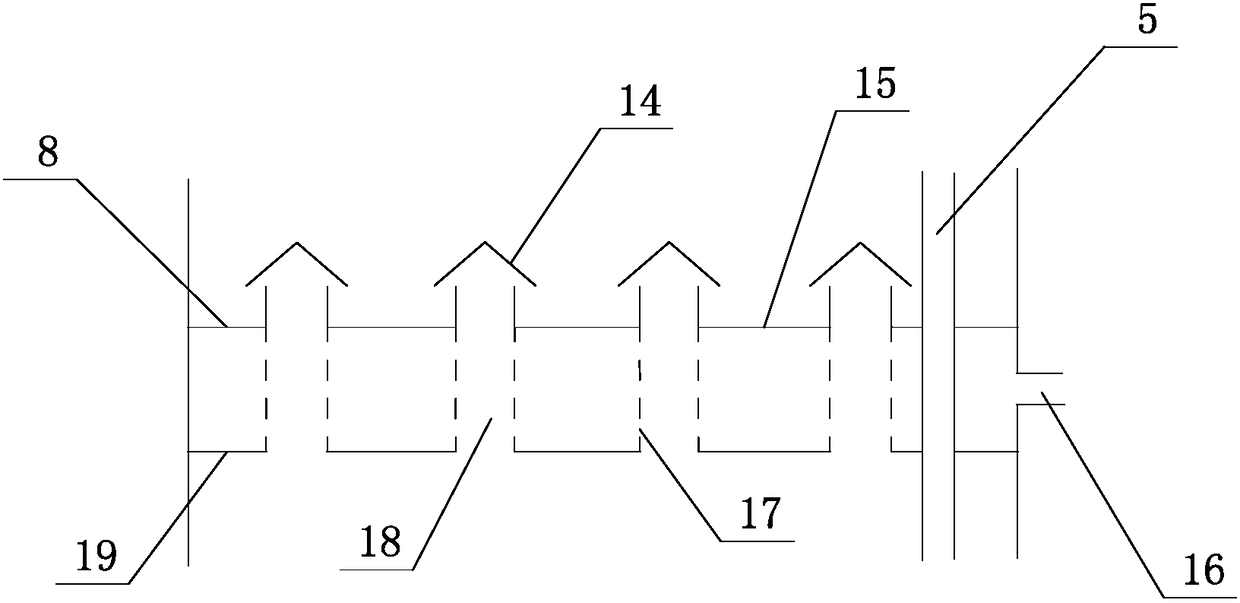
[0026] Such as Figure 1-2 As shown, the ebullating bed reactor of the present invention includes a reactor cylinder 9, the upper end of the reactor cylinder 9 is respectively provided with a catalyst inlet 13 and a gas outlet 1, and the lower end of the reactor cylinder 9 is provided with a material inlet 6 and a catalyst Outlet 5, a three-phase separator is arranged on the upper side of the reactor cylinder 9, and a gas-liquid distributor 8 is arranged on the lower side of the reactor cylinder 9, and the gas-liquid distributor 8 includes a material distribution pipe 18, an upper tower The tray 15 and the lower tray 19, the upper tray 15 and the lower tray 19 form a double-layer tray structure, and the double-layer tray structure of the gas-liquid distributor 8 is tightly fixed on the inner wall of the reactor cylinder 9, and the upper tower A gap is formed between the tray 15 and the lower tray 19, the material distribution pipe 18 runs through the upper tray 15 and the lowe...

Embodiment 2

[0036] On the basis of Example 1, the separation effect of the three-phase separator is simulated by using a cold model. The size of the cold mold device is: the inner diameter of the reactor cylinder 9 is 200mm, the height of the reactor cylinder 9 is 3500mm, the height of the three-phase separator is 400mm, the diameter of the straight cylinder section of the outer cylinder 11 of the three-phase separator is 300mm, and the inner cylinder 12 The annular gap distance between the outer cylinder 11 and the outer cylinder 11 is 80mm, the height difference between the upper end of the inner cylinder 12 and the upper end of the outer cylinder 11 is 60mm, the gap between the lower end opening of the inner cylinder 12 and the contraction section of the outer cylinder 11 is 60mm, and the outer cylinder 11 The diameter of the opening at the lower end of the contraction section is 90 mm, and the contraction angle (the acute angle included angle between the straight tube section and the t...


PUM

PropertyMeasurementUnit
heightaaaaaaaaaa
diameteraaaaaaaaaa
diameteraaaaaaaaaa

Abstract

The invention relates to the technical field of boiling beds, in particular to a boiling bed reactor. The boiling bed reactor comprises a reactor cylinder, a three-phase separator is arranged at the upper side inside the reactor cylinder, a gas-liquid distributor is arranged at the lower side inside the reactor cylinder and comprises a material distributing pipe, an upper tray and a lower tray, the upper tray and the lower tray form a dual-layer tray structure, gaps are formed by the upper tray and the lower tray, the material distributing pipe penetrates through the upper tray and the lower tray, a hood is arranged at an upper end opening of the material distributing pipe, a pipe wall opened hole is formed in the portion, between the upper tray and the lower tray, of the material distributing pipe, and a circulating oil reactor inlet is further formed between the upper tray and the lower tray. By means of the boiling bed reactor, a solid catalyst which is separated from the three-phase separator is settled in the radial center area of the reactor and flows back into the reactor, the problem that when the three-phase separator is filled with a large dosage of catalyst, the settlingand backflow resistance of the catalyst is large is solved, and it is guaranteed that the three-phase separator still has a good separating effect when filled with a large dosage of catalyst.

Description

technical field [0001] The invention relates to the field of fluidized bed technology, in particular to a fluidized bed reactor. Background technique [0002] Ebullated bed hydrogenation reaction refers to the process of hydrogenation reaction of feedstock oil (mainly in liquid phase) and hydrogen (gas phase) on catalyst (solid phase). Hydrogenation reaction mainly occurs in hydrodesulfurization, hydrodenitrogenation and hydrodeoxygenation , hydrogenation saturation, hydrocracking, etc. The reactor operates in the boiling state of gas, liquid and solid. The catalyst is in a boiling state driven by the raw material oil and hydrogen entering from the bottom of the reactor, which is in a completely different fluid state from the fixed bed reactor. The ebullated bed hydrogenation reaction can process low-quality feedstock oil with high metal and high asphaltene content. The reaction has the characteristics of small pressure drop, uniform temperature, and online catalyst additio...

Claims


Application Information

Patent Timeline
Patent Type & Authority Applications(China)
IPC IPC(8): B01J8/38C10G45/20
CPCB01J8/386C10G45/20C10G2300/202
Inventor 王小英
Owner 上海竣铭化工工程设计有限公司
Why Eureka
Try Eureka