
Integrated wall-mounted medical nursing system

A nursing system, wall-mounted technology, applied in nursing facilities, medical science, hospital equipment, etc., can solve the problems of exposed gas terminal pollution, inconvenient maintenance and repair, high labor intensity, etc. The effect of overhauling and eliminating hygienic dead ends

Pending Publication Date: 2018-05-29
黑龙江省医用氧气总公司
View PDF0 Cites 0 Cited by
  • Summary
  • Abstract
  • Description
  • Claims
  • Application Information

AI Technical Summary

Problems solved by technology

[0004] The purpose of the present invention is to solve the poor safety of the existing medical equipment belts, the exposed gas terminal is very easy to cause pollution, the labor intensity of the assembly and installation of workers is high, it is not easy to maintain and overhaul, and it is easy to cause damage to the wall when the hospital bed is moved. Damage problem, and then provide a whole wall-mounted medical care system

Method used


Image

  • Integrated wall-mounted medical nursing system
  • Integrated wall-mounted medical nursing system
  • Integrated wall-mounted medical nursing system

Examples


specific Embodiment approach 1

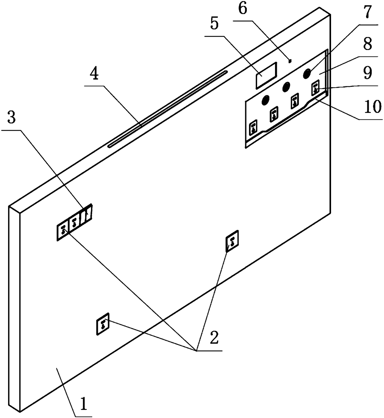
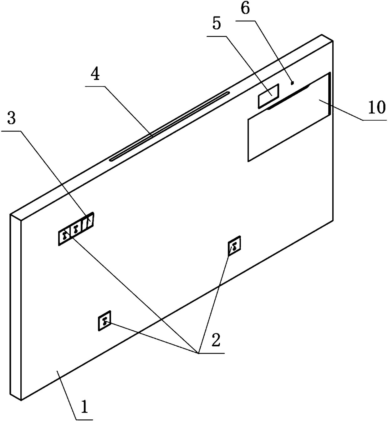
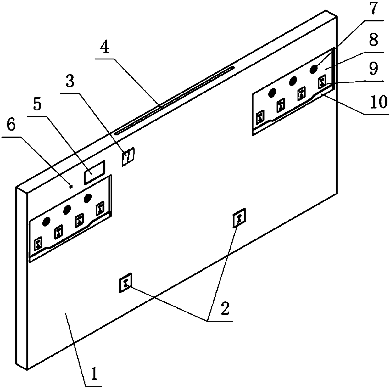
[0029] Specific implementation mode one: combine Figure 1 to Figure 8 Describe this embodiment, an integral wall-mounted medical care system of this embodiment, which includes a panel 1, a gas pipeline terminal socket 7, a cavity module 8, a door panel sliding mechanism 10, a skeleton 11, strong and weak current circuits, and socket module I2 , strong and weak current circuit and socket module Ⅱ6, strong and weak current circuit and socket module Ⅲ9, lighting module, communication call system and pendant installation components,

[0030] A panel 1 is installed on the skeleton 11 welded by multiple beams 16 and multiple longitudinal beams. The panel 1 includes a front, top, bottom and two sides. The panel 1 has an integrated structure, and the lighting module is installed on the panel 1. The cavity module 8 is arranged on the front side of the panel 1. The cavity module 8 is embedded in the panel 1 and fixed on the frame 11. The strong and weak current circuits, the socket mod...

specific Embodiment approach 2

[0031] Specific implementation mode two: combination Figure 8To illustrate this embodiment, the door panel sliding mechanism 10 of this embodiment includes stainless steel wire 13, door panel 14, sliding sleeve 15, pulley assembly 17, two guide rod columns 18, coil spring power assembly 19, wire fixing seat 20 and the main slide module. frame 21, two guide rod columns 18 are installed between the two beams 16 of the skeleton module, the two guide rod columns 18 are arranged in parallel, one end of the two guide rod columns 18 is affixed to the upper beam 16, and the two guide rod columns The other end of 18 is fixedly connected with the lower crossbeam 16, the two guide rod columns 18 are provided with sliding sleeves 15, the door panel 14 is fixedly connected on the sliding sleeves 15, the wire fixing seat 20 is installed on the door panel 14, and the pulley assembly 17 is fixed on the upper On the beam 16, the main frame of the sliding module 21 is arranged on the back of t...

specific Embodiment approach 3

[0032] Specific implementation mode three: combination Figure 8 To describe this embodiment, the coil spring power assembly 19 of this embodiment is provided with a one-way rotation damper, and the one-way rotation damper is built into the winding roller of the coil spring power assembly 19 . In this way, the one-way rotary damper can avoid adverse reactions such as excessive speed, sudden stop, vibration or noise when the control door panel is automatically closed. Other compositions and connections are the same as those in Embodiment 1 or Embodiment 2.


PUM


Abstract

The invention relates to the technical field of medical equipment, in particular to an integrated wall-mounted medical nursing system, and solves the problem that existing medical equipment has poor safety, exposed gas terminals are highly prone to causing pollution, labor intensity is high for workers to perform assembling and mounting, maintenance is inconvenient and a sickbed easily causes damage to a wall when moved. A panel is mounted on a frame, a lighting module is mounted on the panel, a cavity module is embedded in the panel and fixed to the frame, both a strong-weak power circuit andsocket module III and a gas pipe terminal socket are mounted on the cavity module, a cavity unit is provided with a door plate sliding mechanism that is fixed to the frame, the upper portion of the cavity module is provided with a strong-weak power circuit and socket module II and a communications call system, and the frame is fixedly connected with a ward wall through a hanger mounting component. The integrated wall-mounted medical nursing system has improved safety, durability and practicality and is more convenient for medical staff and patients to use.

Description

technical field [0001] The invention relates to the technical field of medical equipment, in particular to an integral wall-mounted medical nursing system. Background technique [0002] Medical equipment belts are commonly used medical facilities in wards. They are mainly used in hospital wards, emergency rooms, treatment rooms, and delivery rooms. They integrate medical gas terminals (oxygen, compressed air, vacuum, etc.), patient information (calling) systems, and power supplies. Sockets, telecommunications network interfaces, lighting and other components are fixed on the bedside wall of the hospital bed to ensure the safety of the medical environment; Safety accidents occur; moreover, the shells of traditional equipment belts are mostly made of multiple modules, which require cutting, assembly and installation at the construction site, which requires a large amount of work, is time-consuming and labor-intensive, and is easy to damage the surface coating of the product; i...

Claims


Application Information

Patent Timeline
Patent Type & Authority Applications(China)
IPC IPC(8): A61G12/00
CPCA61G12/005
Inventor 甘劲松刘宏范旭欣
Owner 黑龙江省医用氧气总公司
Learn More