Eureka AIR delivers breakthrough ideas for toughest innovation challenges, trusted by R&D personnel around the world.

Control device for rotationally and continuously producing alloy and equipment thereof

A control device and a technology for producing alloys, applied in metal processing equipment, safety devices, casting equipment, etc., can solve the problems of long production cycle, high mold cost, low production efficiency, etc., and achieve short production cycle and high control precision , the effect of high production efficiency

Pending Publication Date: 2018-05-29
广西欧迪姆重工科技有限公司
View PDF18 Cites 1 Cited by
  • Summary
  • Abstract
  • Description
  • Claims
  • Application Information

AI Technical Summary

Problems solved by technology

The traditional method has the following disadvantages. First, the high-temperature liquid metal is directly washed to the bottom of the ingot mold, resulting in severe burn damage to the mold and high mold cost per unit product; second, the liquid metal condenses for a long time and serious composition segregation occurs; third, the production cycle is long ; Fourth, labor productivity is particularly low
Taking ferroalloy casting as an example, it takes up to 24-36 hours from casting to processing into a qualified finished product, and the cost of the mold for a ton of alloy products reaches 5-20 yuan; the composition of the product is extremely uneven, and the composition of different parts varies greatly, some as high as More than 10%, can not meet user needs
Some enterprises adopt the chain plate casting machine, and the production efficiency has been greatly improved, but the problem of high mold cost has not been solved, and this method cannot produce high-quality casting rods
[0003] The existing alloy production system generally uses a chain plate casting machine, and its control part is relatively simple, and does not require too many components for simultaneous control, but its production efficiency is relatively low and the powder rate is high

Method used


Image

  • Control device for rotationally and continuously producing alloy and equipment thereof
  • Control device for rotationally and continuously producing alloy and equipment thereof
  • Control device for rotationally and continuously producing alloy and equipment thereof

Examples


Embodiment Construction

[0027] The present invention will be further described below in conjunction with embodiment.

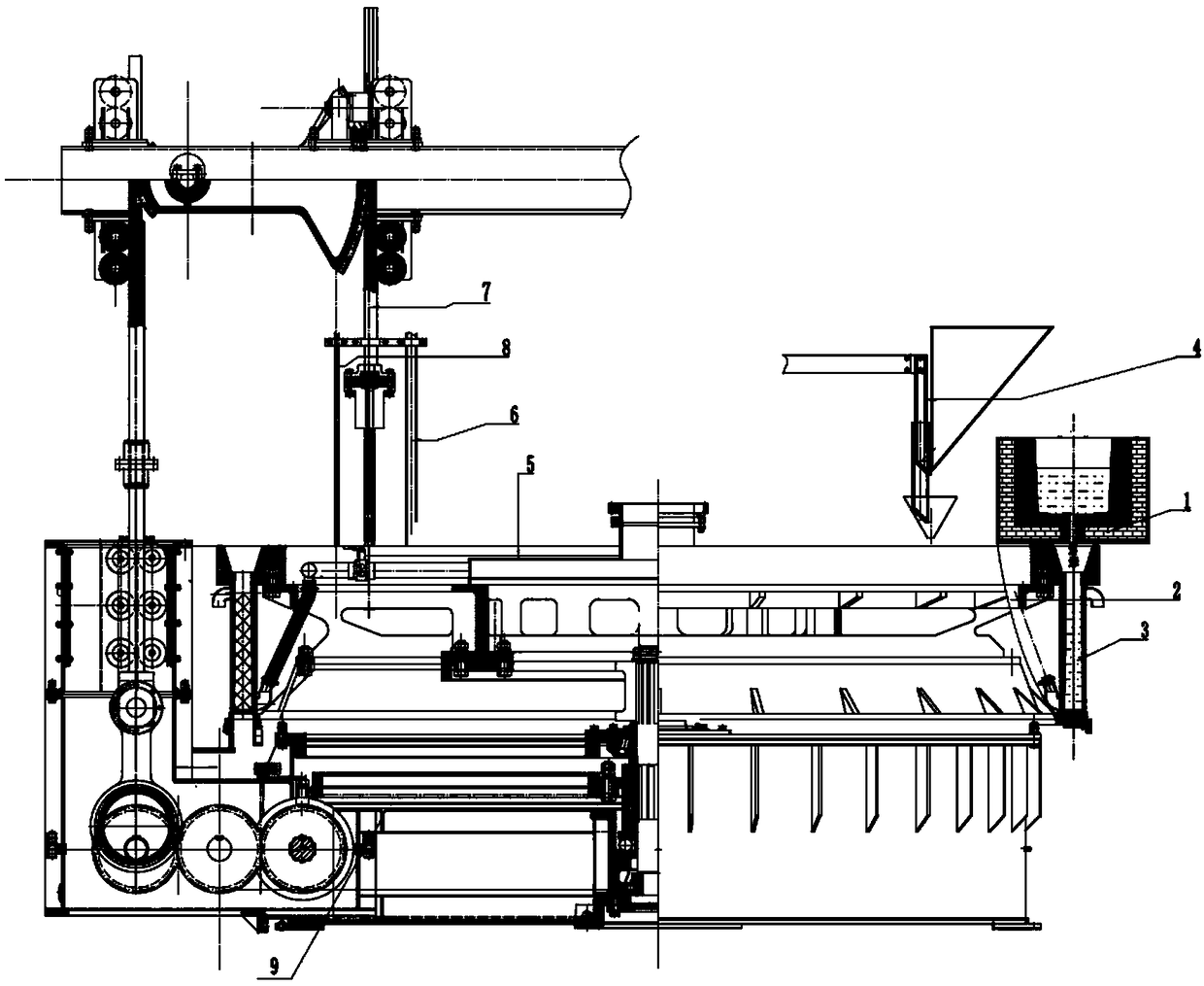
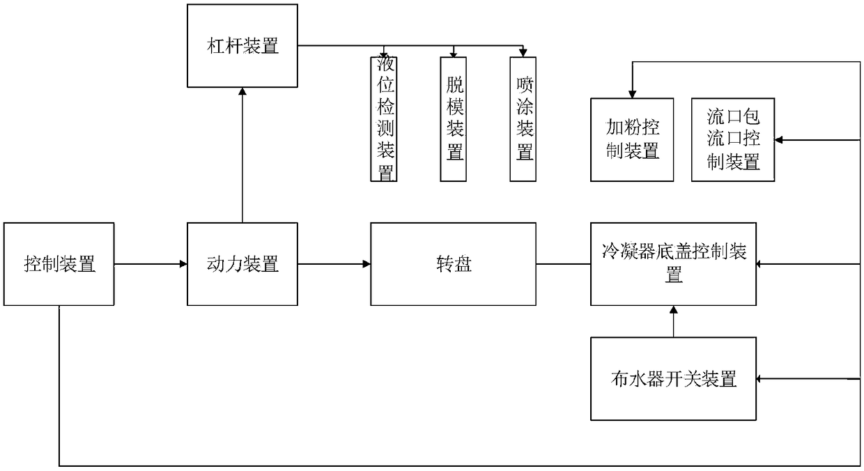
[0028] Such as figure 2 As shown, a control device for rotary continuous production of alloys, including a control device, a power device, a lever device, a water distributor switch device, a powder feeding control device, a condenser bottom cover control device and a spout bag spout control device.

[0029] The output end of the control device is respectively connected with the power device, the switch device of the water distributor, the control device of the bottom cover of the condenser and the flow port control device of the orifice bag. The control device includes a microprocessor, a clock circuit and a motor drive circuit, the clock circuit is connected with the microprocessor, and the microprocessor is connected with the motor through the motor drive circuit. The microprocessor uses STM32 series single-chip microcomputer chips, and the motor drive circuit uses a multi-chann...


PUM

PropertyMeasurementUnit
diameteraaaaaaaaaa
heightaaaaaaaaaa

Abstract

The invention provides a control device for rotationally and continuously producing alloy and equipment thereof, belonging to the technical field of liquid alloy solidification. The control device comprises a control device, a power device, a lever device, a water distributor switch device, a condenser bottom cover control device and a drainage port package drainage port control device. The equipment comprises a drainage port package, a turnplate, a condenser, a powder adding device, a water distributor, a liquid level detector, a punch needle, a spraying device, a power device and a control device. The equipment can be used for continuously producing compact casting rods or granular materials in large batches, and can meet requirement on production of nonferrous metals and steel ingots inlarge, medium and small batches; the equipment improves production efficiency by more than 10 times compared with fixed type ingot casting production equipment used domestically at present.

Description

technical field [0001] The invention relates to the technical field of solidification of liquid alloys, in particular to a control device and equipment for rotating and continuously producing alloys. Background technique [0002] At present, most of the ingots produced in the domestic iron and steel metallurgy, non-ferrous metals and mechanical casting industries are to cast liquid metal into steel ingot molds to obtain various ingots of different sizes. The traditional method has the following disadvantages. First, the high-temperature liquid metal directly washes to the bottom of the ingot mold, resulting in serious mold burnout and high mold cost per unit product; second, the liquid metal condenses for a long time, and serious composition segregation occurs; third, the production cycle is long ; Fourth, labor productivity is particularly low. Taking ferroalloy casting as an example, it takes up to 24-36 hours from casting to processing into a qualified finished product, ...

Claims


Application Information

Patent Timeline
Patent Type & Authority Applications(China)
IPC IPC(8): B22D5/04B22D46/00B22D27/04
CPCB22D5/04B22D27/04B22D46/00
Inventor 曾世昭曾少兰毛小诚
Owner 广西欧迪姆重工科技有限公司
Why Eureka
Eureka Blog
Learn More