Double-wheel slot milling machine based on sprocket transmission and milling, and slot forming method

A double-wheel milling and sprocket technology, which is applied to mechanically driven excavators/dredgers, infrastructure engineering, earth movers/shovels, etc., can solve the problem of reducing construction efficiency, affecting construction efficiency, and disturbing the normal operation of peripheral equipment. Work and other problems, to achieve the effect of reducing construction procedures, improving shear strength and anti-seepage effect

Pending Publication Date: 2018-05-29
CHINA RAILWAY ENG MASCH RES & DESIGN INST CO LTD
View PDF4 Cites 2 Cited by
  • Summary
  • Abstract
  • Description
  • Claims
  • Application Information

AI Technical Summary

Problems solved by technology

[0004] Although the above-mentioned several forms have a certain effect on solving the problem of milling blind spots, there are still the following problems: 1) when the swing teeth or the swingable milling wheel swing to the bottom of the support frame, the radius of gyration decreases, and the A raised rock formation is left on the side wall of the milling groove, which will eventually affect the strength and anti-seepage effect of the poured continuous wall joint; 2) The angle of the milling cutter teeth of the oscillating teeth or the oscillating milling wheel during the swing process I

Method used


Image

  • Double-wheel slot milling machine based on sprocket transmission and milling, and slot forming method
  • Double-wheel slot milling machine based on sprocket transmission and milling, and slot forming method
  • Double-wheel slot milling machine based on sprocket transmission and milling, and slot forming method

Examples


Embodiment Construction

[0034] The technical solutions of the present invention will be described in further detail below with reference to the accompanying drawings and embodiments.

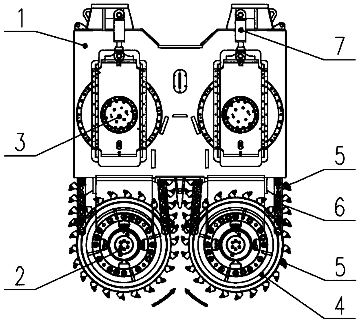
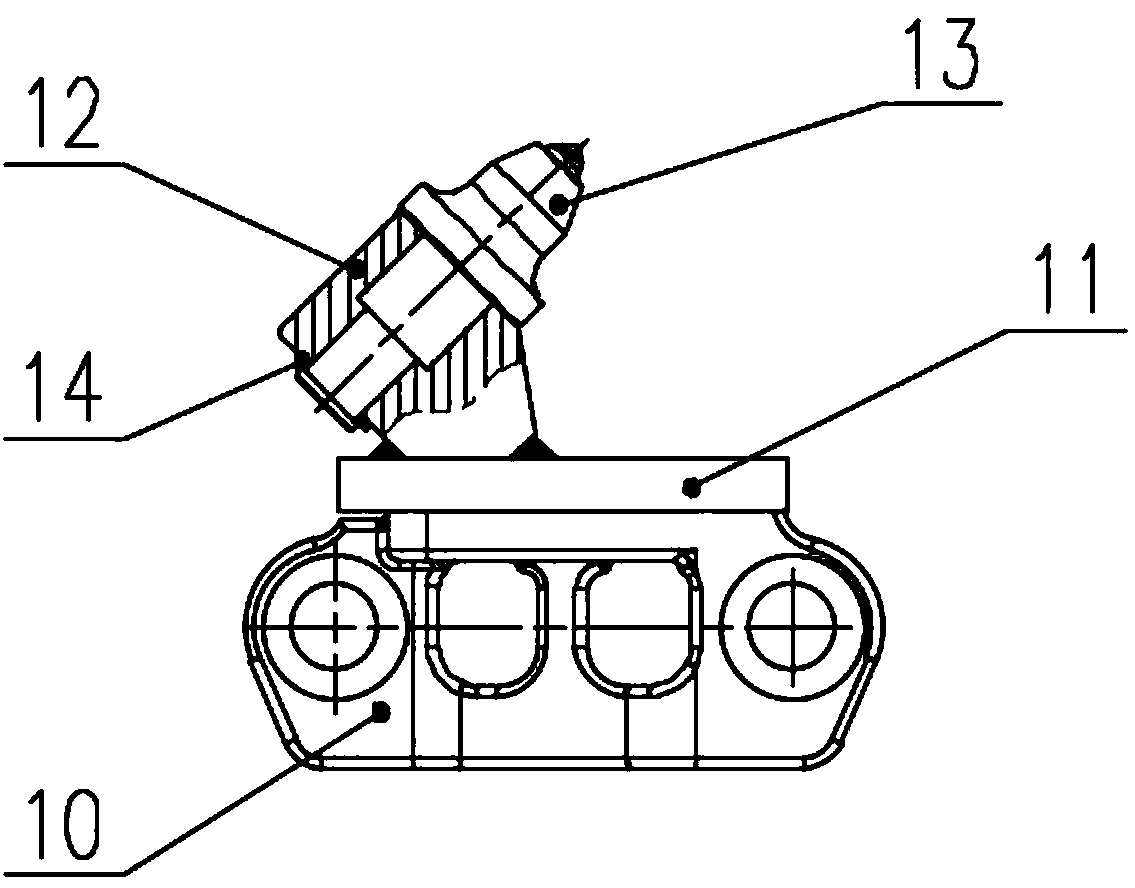
[0035] see figure 1 and 2 , shows the double-wheel milling machine based on sprocket transmission and milling of the present invention.

[0036] The two-wheel milling machine based on sprocket transmission and milling at least includes a support frame 1, a rotating milling wheel 2, a driving wheel 3, a milling wheel hub 4, a plurality of milling cutter teeth 5, sprockets 6, and a sprocket tensioning device 7 and a sprocket roller 8, the rotary milling wheel 2 is two and symmetrically arranged on the left and right sides of the support frame 1, and the driving wheel 3 is also two and symmetrically arranged above the rotary milling wheel 2, the There are two sprocket tensioning devices 7 and they are arranged symmetrically above the driving wheel 3. Each sprocket tensioning device 7 is respectively connected to the dri...


PUM


Abstract

The invention discloses a double-wheel slot milling machine based on sprocket transmission and milling, and a slot forming method. The double-wheel slot milling machine at least comprises a support frame, a rotary milling wheel, a driving wheel, milling wheel hubs, a milling cutter gear, a sprocket, a sprocket tensioning device and a sprocket wheel. The sprocket tensioning device pulls the drivingwheel to move up and down. The sprocket is connected with the driving wheel and the rotary milling wheel in a surrounding mode to achieve driving. A plurality of milling teeth are welded on the peripheral edge of the sprocket. The milling wheel hubs are arranged on two sides of the rotary milling wheel. A plurality of milling teeth are arranged on the circumferences of the milling wheel hubs at intervals. The sprocket wheel is located on the inner side of the sprocket to eject the sprocket outwardly during mounting. The double-wheel slot milling machine has the advantages that technical problems in the prior art are solved, rock stratums below the support frame can be milled completely, smoothness of the side wall of a milling groove is guaranteed, and slurry and rock debris are discharged quickly; triangular grooves can be formed in two sides of the milling groove respectively, and shearing strength and seepage-proofing effect at casted continuous wall joints after slotting are improved greatly.

Description

technical field [0001] The invention relates to the technical field of engineering machinery, in particular to a double-wheel slot milling machine based on chain tooth transmission and milling and a slotting method. Background technique [0002] In the current underground diaphragm wall construction operations, the double-wheel milling machine is the most advanced and widely used construction equipment. Its traditional structure and working principle are as follows: two rotating milling wheels are arranged on the left and right sides of a milling wheel support frame, and the two milling wheels are driven by the driving mechanism to rotate inward from the bottom, relying on the cutting teeth on the rotating milling wheel Mills dirt and rock formations and continuously rolls mud and cuttings out of the bottom of the tank. Since the supporting frame of the milling wheel has a certain thickness, there is a large gap between the hubs of the milling wheel on the front and rear si...

Claims


Application Information

Patent Timeline
IPC IPC(8): E02F5/08E02F3/18E02F3/24E02D5/18
CPCE02D5/187E02F3/188E02F3/243E02F3/246E02F5/08
Inventor 谢继伟周江明李畅哲高大诚刘炎张征明郑泽林李遥
Owner CHINA RAILWAY ENG MASCH RES & DESIGN INST CO LTD
Why Eureka
Try Eureka