Supercharge Your Innovation With Domain-Expert AI Agents!

Rotary flow urea mixing device

A technology of mixing device and urea, which is applied in muffler device, exhaust device, exhaust gas treatment and other directions, can solve the problems of insufficient mixing, short mixing path of ammonia gas and exhaust gas, affecting exhaust gas treatment, etc., to increase the mixing effect and structure. Simple, compact design effects

Inactive Publication Date: 2018-05-29
WUXI WEIFU LIDA CATALYTIC CONVERTER
View PDF5 Cites 5 Cited by
  • Summary
  • Abstract
  • Description
  • Claims
  • Application Information

AI Technical Summary

Problems solved by technology

[0003] The purpose of the present invention is to solve the problem that the mixing path of ammonia gas and tail gas is relatively short in the existing SCR process of treating tail gas, and the insufficient mixing affects the treatment of tail gas. It provides a simple structure and compact design that can improve the mixing effect of ammonia gas and tail gas. Cyclone urea mixing device

Method used


Image

  • Rotary flow urea mixing device
  • Rotary flow urea mixing device
  • Rotary flow urea mixing device

Examples


Embodiment Construction

[0021] The present invention will be further described below with reference to the specific drawings and embodiments.

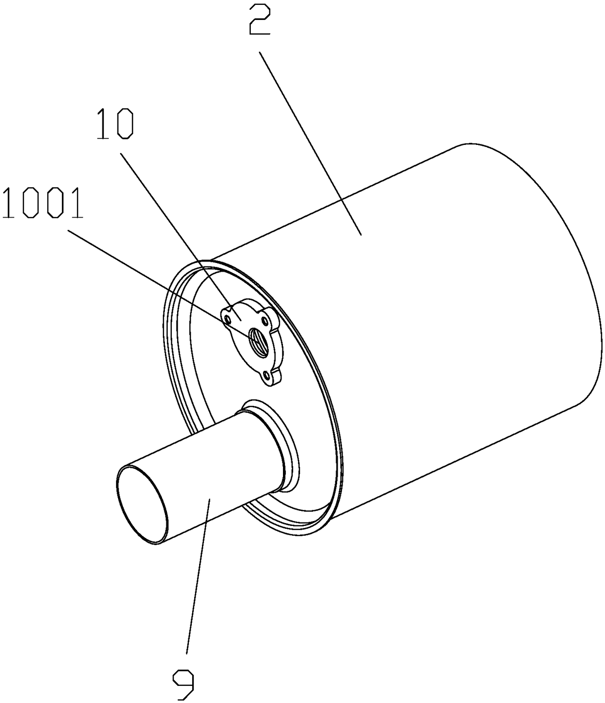
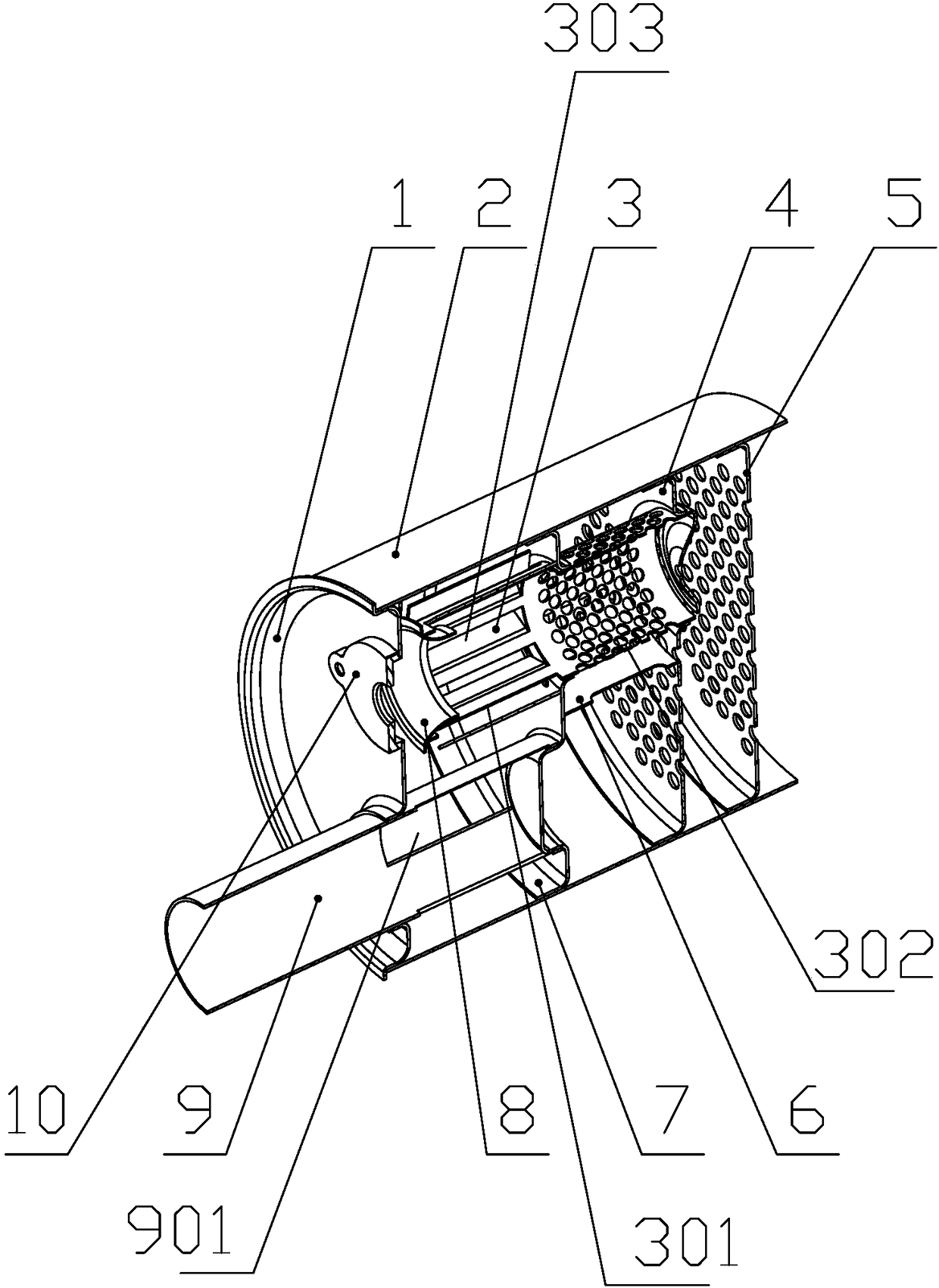
[0022] like figure 1 and figure 2 As shown, the swirl urea mixing device provided by the present invention includes: an end cover 1, a cylinder body 2, a swirl pipe 3, a front porous baffle 4, a rear porous baffle 5, a semicircular baffle 6, a baffle 7, Conical baffle 8, intake pipe 9, urea nozzle mounting seat 10;

[0023] The front end of the cylinder body 2 is provided with an end cap 1 to be closed, and the rear end opening is used as an air outlet; the cylinder body 2 is provided with a partition 7, a front porous partition plate 4 and a rear porous partition plate 5 in order from front to back in the cylinder body 2. The body 2 is divided into a first cavity between the end cap 1 and the separator 7 , a second cavity between the separator 7 and the front porous separator 4 , and a second cavity between the front porous separator 4 and the rear porous...


PUM


Abstract

The invention provides a rotary flow urea mixing device comprising an end cover, a cylinder body, a rotary-flow tube, a front porous separator, a rear porous separator, a separator, an air inlet pipe,and a urea nozzle mounting seat; the front end of the cylinder body is provided with the end cover and a back end opening is used as an air outlet; the cylinder body is internally provided with the separator, the front porous separator, and the rear porous separator in sequence at intervals from front to rear so as to divide the interior of the cylinder body into a first cavity between the separator and the end cover, a second cavity between the separator and the front porous separator, and a third cavity between the front porous cavity separator and the rear porous separator; a front sectionof the air inlet pipe extends out of the first cavity of the cylinder body, and a rear section of the air inlet pipe is arranged in the cylinder body and is provided with a diversion opening communicating with the first cavity of the cylinder body; the front section of the air inlet pipe is provided with an air inlet; the rotary-flow tube is arranged in the cylinder body; the rotary-flow tube includes a rotary-flow section and a porous section, wherein the rotary-flow section is arranged in the first cavity of the cylinder body, and the porous section is arranged in the second cavity of the cylinder body; and the end cover is provided with the urea nozzle mounting seat. The rotary flow urea mixing device can improve the mixing effect of ammonia gas and tail gas.

Description

technical field [0001] The invention relates to a urea mixing device for vehicle exhaust gas treatment, in particular to a swirl urea mixing device. Background technique [0002] With the increasingly stringent diesel engine emission regulations, exhaust aftertreatment technology is a necessary technical measure. SCR can meet the national IV, V and national VI emission standards. The basic principle of SCR is to atomize a 32.5% concentration of urea aqueous solution through the urea injection system (commonly known as urea pump) and then spray it into the exhaust pipe to mix with the engine exhaust. The aqueous solution generates ammonia (NH3) through pyrolysis and hydrolysis. Under the action of a catalyst, ammonia converts harmful nitrogen oxides (NOx) in diesel engine exhaust into harmless nitrogen (N2) and water. Engine exhaust treatment technology SCR The first task of the route is to effectively mix and chemically react the exhaust gas with the ammonia mist, while mai...

Claims


Application Information

Patent Timeline
IPC IPC(8): F01N3/20F01N3/28
CPCF01N3/2066F01N3/2892F01N2570/14F01N2610/02F01N2610/14
Inventor 曲洪亮段一军朱亮吴杰惠志君林浩健徐超郭一博徐文清
Owner WUXI WEIFU LIDA CATALYTIC CONVERTER
Features
  • R&D
  • Intellectual Property
  • Life Sciences
  • Materials
  • Tech Scout
  • Unparalleled Data Quality
  • Higher Quality Content
  • 60% Fewer Hallucinations
Learn More