Supercharge Your Innovation With Domain-Expert AI Agents!

Heat pump system with center supplement gas

A technology of heat pump system and intermediate air supply, which is applied in heat pumps, lighting and heating equipment, and compressors with reversible cycles, etc. It can solve the problems of idle units and waste, reduce usage, reduce energy consumption, and save initial investment cost effect

Pending Publication Date: 2018-05-29
TIANJIN UNIV OF COMMERCE
View PDF0 Cites 0 Cited by
  • Summary
  • Abstract
  • Description
  • Claims
  • Application Information

AI Technical Summary

Problems solved by technology

[0003] However, when two-stage compression is used to realize heating in winter, if the system is designed to meet the heating load requirements of the outdoor temperature at -25°C, the cooling capacity configured by the system in summer cooling is far greater than the cooling load of the building. During operation, more than half of the units in the system will be idle, resulting in waste

Method used


Image

  • Heat pump system with center supplement gas
  • Heat pump system with center supplement gas
  • Heat pump system with center supplement gas

Examples


Embodiment 1

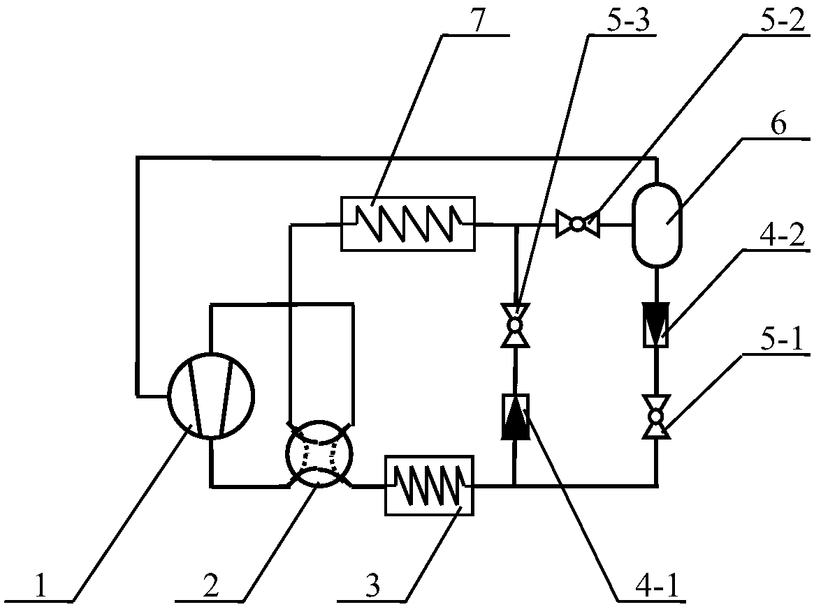
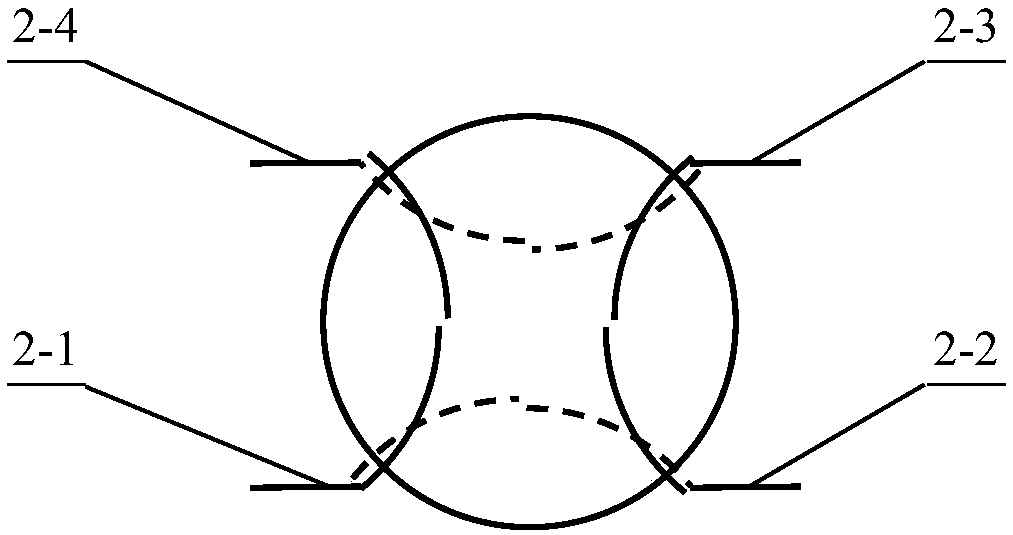
[0025] The schematic diagram of the heat pump system with intermediate air supply using three throttle valves in the present invention is as follows figure 1 As shown, it includes compressor 1, four-way reversing valve 2, outdoor heat exchanger 3, indoor heat exchanger 7, first throttle valve 5-1, second throttle valve 5-2, third throttle valve 5-3, the first valve 4-1, the second valve 4-2 and the intercooler 6, the exhaust end of the compressor 1 is connected to the first interface 2-1 of the four-way reversing valve 2, The suction end of the compressor 1 is connected to the third port 2-3 of the four-way reversing valve 2, and the second port 2-2 of the four-way reversing valve 2 passes through the outdoor heat exchanger 3 They are respectively connected to the outlet of the first throttle valve 5-1 and the inlet of the first valve 4-1, and the liquid outlet of the intercooler 6 is connected to the first throttle valve 5 through the second valve 4-2. -1 inlet connection; t...

Embodiment 2

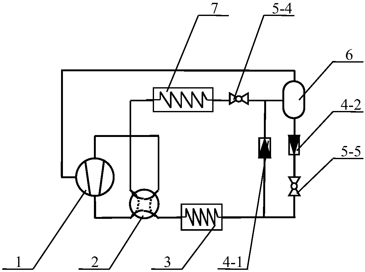
[0030] The schematic diagram of the heat pump system with intermediate gas supply using two throttle valves in the present invention is as follows figure 2 As shown, it includes compressor 1, four-way reversing valve 2, outdoor heat exchanger 3, indoor heat exchanger 7, intercooler 6, first valve 4-1, second valve 4-2, fourth throttling Valve 5-4 and fifth throttle valve 5-5, the discharge end of the compressor 1 is connected to the first interface 2-1 of the four-way reversing valve 2, the suction end of the compressor 1 It is connected with the third port 2-3 of the four-way reversing valve 2, and the second port 2-2 of the four-way reversing valve 2 is respectively connected with the fifth throttle valve through the outdoor heat exchanger 3 The outlet of 5-5 is connected to the inlet of the first valve 4-1, and the liquid outlet of the intercooler 6 is connected to the inlet of the fifth throttle valve 5-5 through the second valve 4-2; the intercooler The exhaust port of ...


PUM


Abstract

The invention discloses a heat pump system with center supplement gas, aiming to improve heat pump efficiency, reduce unit quantity and reduce initial system investment when heat source temperatures are low in winter. An exhaust end of a compressor is connected with a first connector of a four-way reversing valve. A suction end of the compressor is connected with a third connector of the four-wayreversing valve. A second connector of the four-way reversing valve is connected with an outlet of a first throttle valve and an inlet of a first valve through an outdoor heat exchanger. A liquid outlet of an intercooler is connected with an inlet of the first throttle valve through a second valve. An exhaust outlet of the intercooler is connected with a gas supplement inlet of the compressor. A second connector of an indoor heat exchanger is connected with an inlet of a second throttle valve and an outlet of a third throttle valve. An outlet of the second throttle valve is connected with an inlet of the intercooler. An inlet of the third throttle valve is connected with an outlet of the first valve. A first connector of the indoor heat exchanger is connected with a fourth connector of thefour-way reversing valve.

Description

technical field [0001] The invention relates to a heat pump unit, more specifically, to a heat pump system that adopts single-stage compression for cooling in summer and can realize heating with intermediate supplementary air in winter, so as to improve the heating efficiency of the heat pump system in winter when the temperature of the heat source is low . Background technique [0002] With the continuous improvement of environmental protection requirements, air source heat pumps are being widely used due to their technical characteristics of energy saving and environmental protection. When the single-stage compression cycle is used for heating in winter, its application is limited due to its high compression ratio and low system efficiency. In order to improve the efficiency of the air source heat pump system and realize heating at an outdoor temperature of -25°C, a two-stage compression cycle is adopted. [0003] However, when two-stage compression is used to realize he...

Claims


Application Information

Patent Timeline
Patent Type & Authority Applications(China)
IPC IPC(8): F25B13/00F25B30/02F25B41/06F25B41/20F25B41/30
CPCF25B13/00F25B30/02F25B41/37F25B41/31
Inventor 杨永安赵瑞昌陈剑波严雷陈少为
Owner TIANJIN UNIV OF COMMERCE
Features
  • R&D
  • Intellectual Property
  • Life Sciences
  • Materials
  • Tech Scout
  • Unparalleled Data Quality
  • Higher Quality Content
  • 60% Fewer Hallucinations
Learn More