

Plunger
The technology of a plunger and a plunger base body is applied to a plunger. It can solve the problems affecting the properties of the reinforcement layer, cracks in the cladding layer, and limited casting waste heat, and achieve excellent wear resistance and mechanical properties, dense reinforcement layer, and reduced thermal stress.
- Summary
- Abstract
- Description
- Claims
- Application Information
AI Technical Summary
Problems solved by technology
Method used
Image

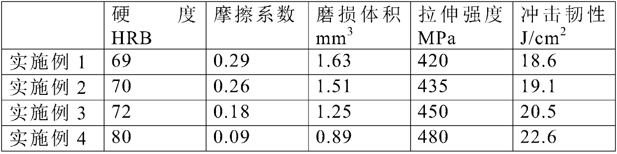
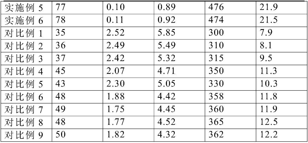
Examples
Embodiment 1
[0019] The plunger matrix of the plunger in this embodiment is composed of the following components in weight percentage: C 0.4%, Mn 0.8%, Cr 5.0%, Cu 0.9%, Ti 1.2%, V: 0.8%, Nb: 0.5%, Al 1.2 %, the balance is Fe. Weigh the alloy steel raw material according to the above ratio, put it into a vacuum melting furnace, heat it to 800°C to melt, and cast the plunger matrix; place the plunger matrix as an inlay in the mold, heat the alloy powder to 1100°C, and cast it on the In the mold of the plug base, cool naturally; heat up to 1500°C, keep warm for 1.5h, place in cold water for quenching, then heat to 400°C at a speed of 0.3°C / s, keep warm for 4h, and cool naturally to get the plunger. The alloy powder is 40 parts by weight of Fe, 3 parts of Hf, 5 parts of Os, 6 parts of B, 3 parts of Sc, 2 parts of V, and 2 parts of silicon dioxide particles. Weigh each component, put Fe, Hf, Os, B, Sc and V into a ball mill and mill for 3 hours, vacuum dry for 40 minutes, sieve to obtain a 40...
Embodiment 2
[0021] The plunger matrix of the plunger in this embodiment is composed of the following components in weight percentage: C 0.4%, Mn 0.8%, Cr 5.0%, Cu 0.9%, Ti 1.2%, V: 0.8%, Nb: 0.5%, Al 1.2 %, the balance is Fe. Weigh the alloy steel raw material according to the above ratio, put it into a vacuum melting furnace, heat it to 800°C to melt, and cast the plunger matrix; place the plunger matrix as an inlay in the mold, heat the alloy powder to 1100°C, and cast it on the In the mold of the plug base, cool naturally; heat up to 1500°C, keep warm for 1.5h, place in cold water for quenching, then heat to 400°C at a speed of 0.3°C / s, keep warm for 4h, and cool naturally to get the plunger. The alloy powder is 40 parts by weight of Fe, 3 parts of Hf, 5 parts of Os, 6 parts of B, 3 parts of Sc, 2 parts of V, and 2 parts of silicon dioxide particles. Weigh each component, put Fe, Hf, Os, B, Sc and V into a ball mill and mill for 3 hours, vacuum dry for 40 minutes, sieve to obtain a 10...
Embodiment 3
[0023] The plunger matrix of the plunger in this embodiment is composed of the following components by weight percentage: C 0.4%, Mn 0.8%, Cr 5.0%, Cu 0.9%, Ti 1.2%, Al 1.2%, and the balance is Fe. Weigh the alloy steel raw material according to the above ratio, put it into a vacuum melting furnace, heat it to 800°C to melt, and cast the plunger matrix; place the plunger matrix as an inlay in the mold, heat the alloy powder to 1100°C, and cast it on the In the mold of the plug base, cool naturally; heat up to 1500°C, keep warm for 1.5h, place in cold water for quenching, then heat to 400°C at a speed of 0.3°C / s, keep warm for 4h, and cool naturally to get the plunger. The alloy powder is 40 parts by weight of Fe, 3 parts of Hf, 5 parts of Os, 6 parts of B, 3 parts of Sc, 2 parts of V, and 2 parts of silicon dioxide particles. Weigh each component, put Fe, Hf, Os, B, Sc and V into a ball mill and mill for 3 hours, vacuum dry for 40 minutes, sieve to obtain a 400-mesh mixture, t...
PUM
 Abstract
Description
Claims
Application Information