Automatic charging device for single crystal furnace and operation method of automatic charging device

An automatic feeding device and single crystal furnace technology, applied in the direction of single crystal growth, single crystal growth, polycrystalline material growth, etc., can solve the phenomenon of broken ridge line or broken crystal line, polycrystalline growth, feeding quantity and crystal growth Match the quantity and other issues to achieve the effect of stable liquid level and avoid splashing

Pending Publication Date: 2018-06-01
JIANGSU BAIR PHOTOELECTRIC EQUIP CO LTD
View PDF12 Cites 16 Cited by
  • Summary
  • Abstract
  • Description
  • Claims
  • Application Information

AI Technical Summary

Problems solved by technology

The inventors of the present invention have found that: in principle, as much as the crystal growth is required, the amount of feeding is the same, but the current artificial control feeding method is difficult to match the amount of feeding with the amount of crystal growth
When the amount of feed is greater than the crystal growth rate, the liquid level of the liquid silicon material in the crucible will rise, and the distance between the liquid level and the top of the crucible will become smaller; The liquid level of the liquid silicon material decreases, and the distance between the liquid level and the top of the crucible will increase, which will cause the crystal to grow unstable, and even polycrystalline growth phenomenon (also known as broken ridge phenomenon or broken crystal line phenomenon)

Method used


Image

  • Automatic charging device for single crystal furnace and operation method of automatic charging device
  • Automatic charging device for single crystal furnace and operation method of automatic charging device
  • Automatic charging device for single crystal furnace and operation method of automatic charging device

Examples


Embodiment 1)

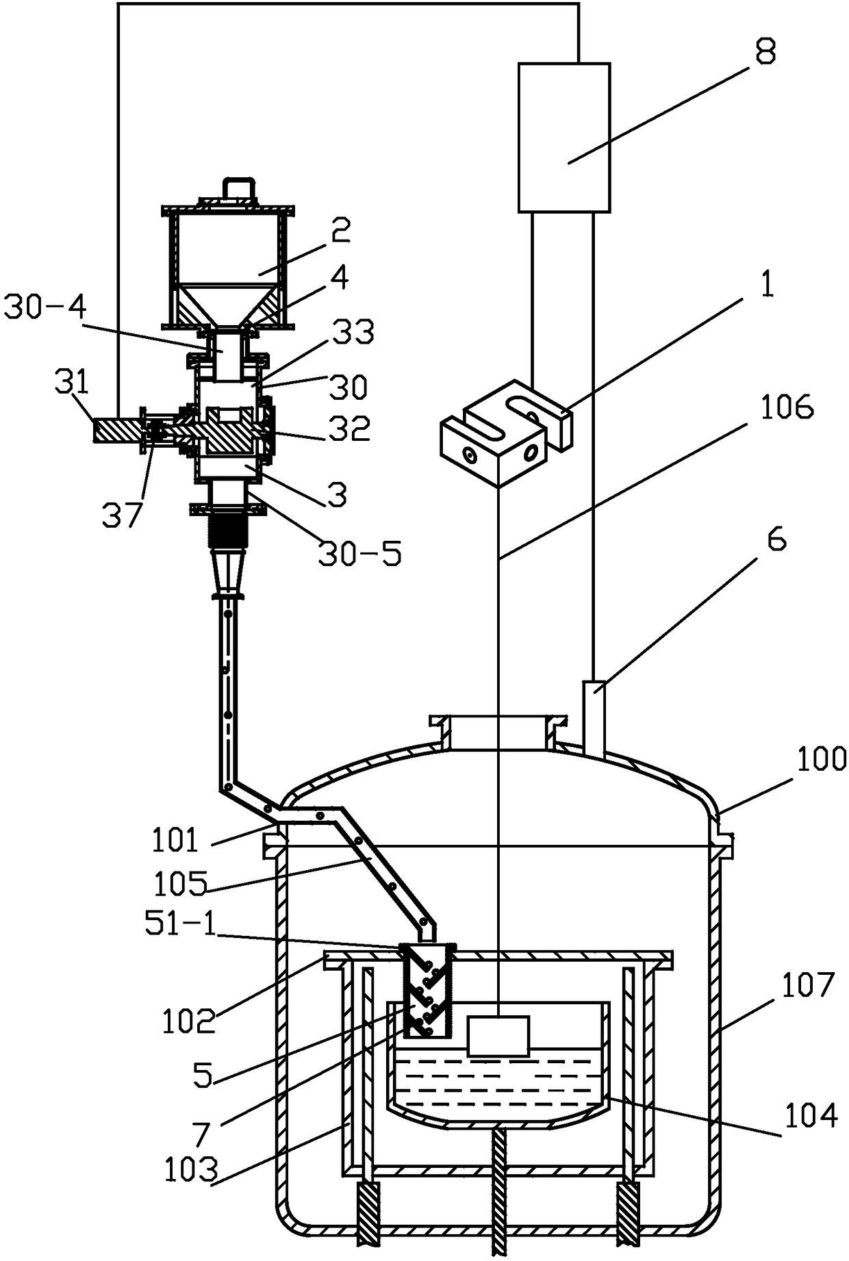
[0041] See figure 1 The automatic feeding device of the single crystal furnace in this embodiment includes a weighing mechanism 1 , a material storage box 2 , a feeding mechanism 3 , a valve, a material buffer device 5 , a liquid level tracking mechanism 6 and a main controller 8 . The valves include a first valve 4 and a second valve. The weighing signal output terminal of the weighing mechanism 1, the control terminal of the motor, the respective control terminals of the first valve 4 and the second valve, and the output terminal of the laser ranging signal of the liquid level tracking mechanism 6 are all electrically connected to the main controller or wireless signal connect.

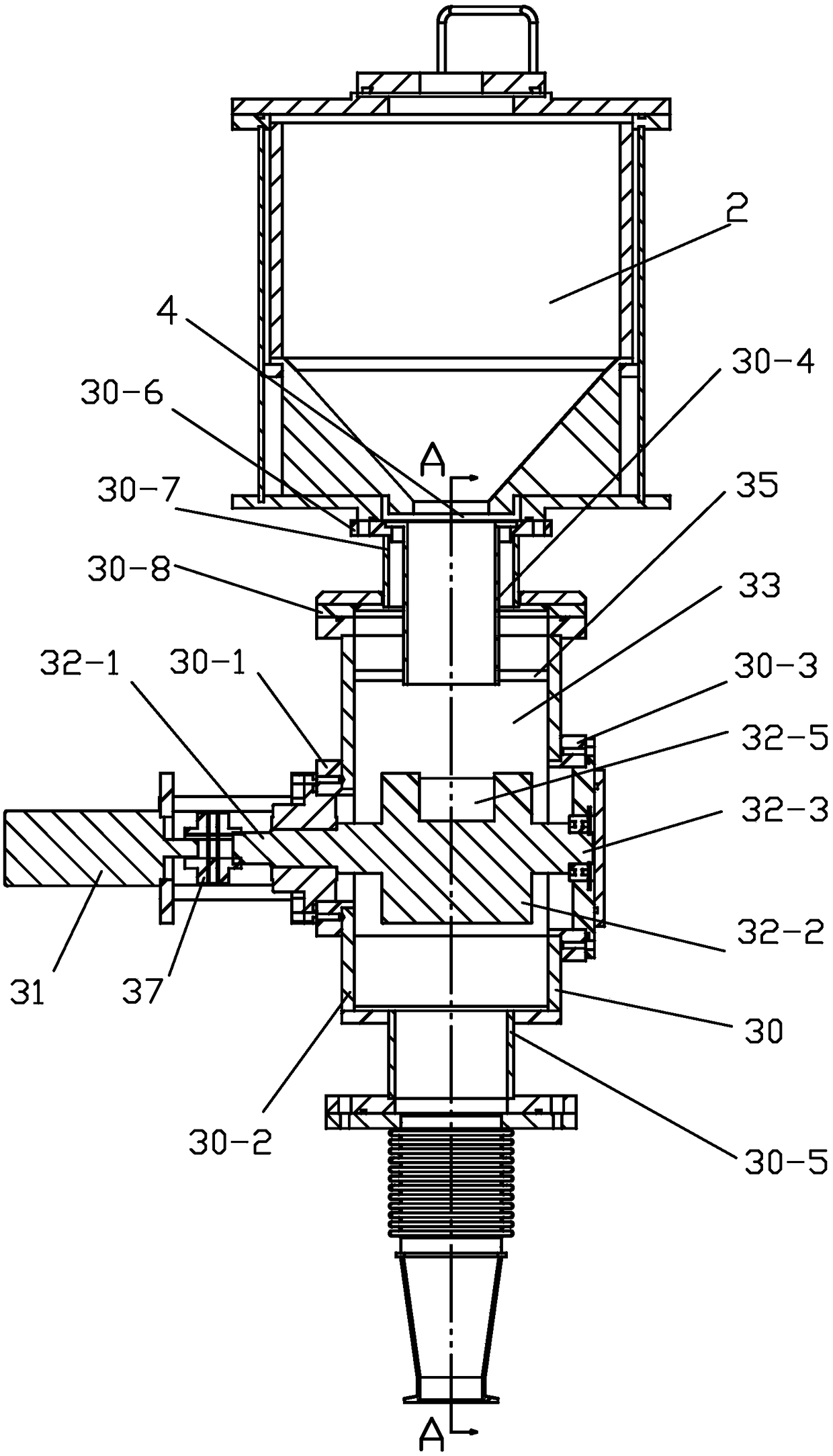
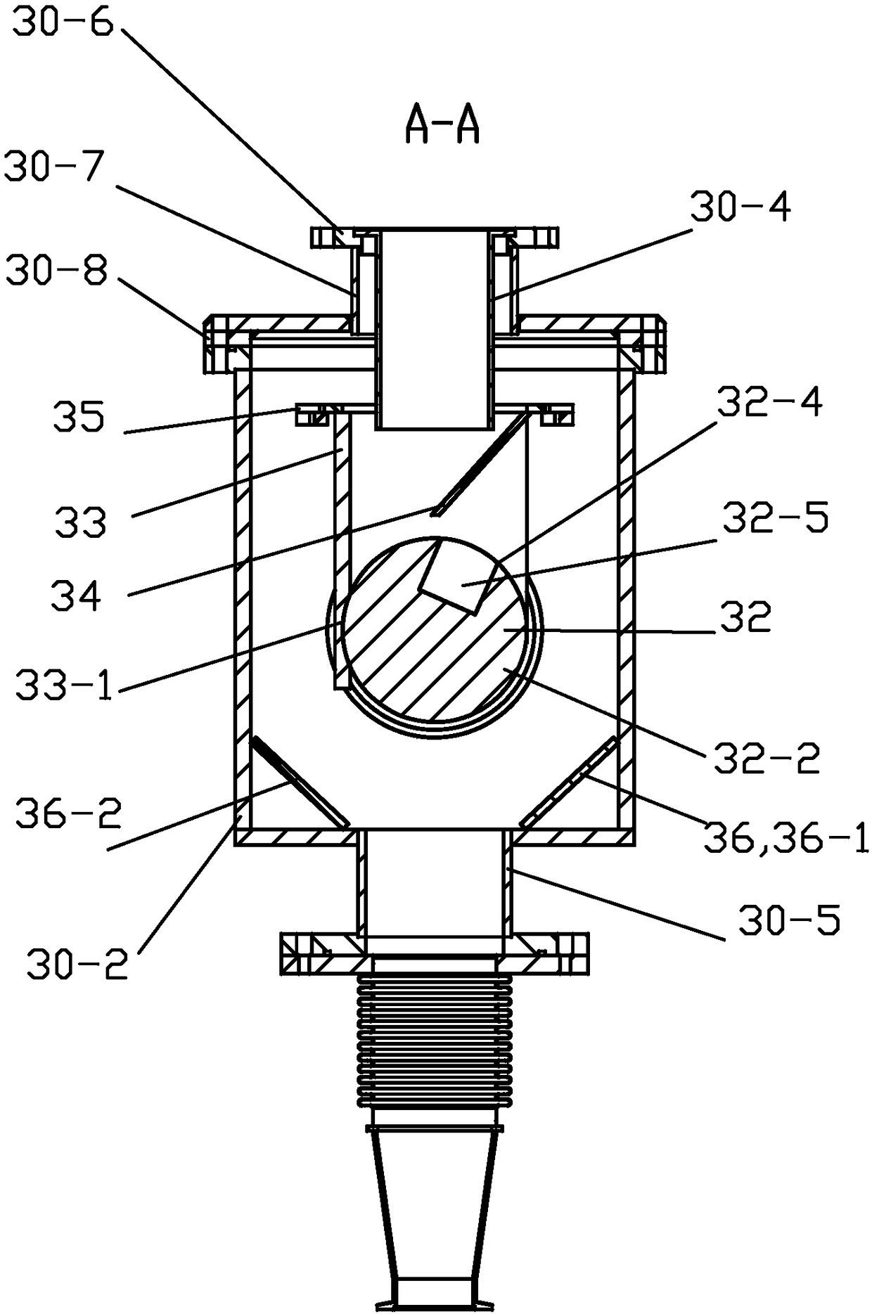
[0042] See Figure 1 to Figure 3 , the feeding mechanism 3 includes a material box 30 , a motor 31 , a rotating shaft 32 , a baffle plate 33 , a material guide plate 34 , a connecting plate 35 , a guide plate 36 and a coupling 37 . The materials of the material box 30, the rotating shaft 32, the ...


PUM

PropertyMeasurementUnit
heightaaaaaaaaaa

Abstract

The invention relates to an automatic charging device of a single crystal furnace and an operation method of the automatic charging device. The automatic charging device comprises a weighing mechanism, a main controller, a charging mechanism and a storage box, wherein the charging mechanism comprises a material box, a motor, a rotating shaft and a baffle; a feeding port and a discharging port areformed in the material box; the rotating shaft is rotationally connected onto the material box and fixedly connected with an output shaft of the motor, an opening is formed in the periphery of the axial middle of the rotating shaft, and the opening extends inwards in the radial direction to form a bin opening; the baffle is fixedly connected onto the material box and close to the periphery of theaxial middle of the rotating shaft; the storage box is fixedly connected at the feeding port of the material box and communicated with the feeding port. The motor and the weighing mechanism are both electrically connected with the main controller or connected with the main controller through wireless signals. By the aid of the single crystal furnace comprising the automatic charging device, in thecontinuous drawing process of single crystal rods, the liquid level of a liquid silicon material in a crucible can be kept stable during continuous charging, crystals can grow stably, and the phenomenon of polycrystalline growth can be avoided.

Description

technical field [0001] The invention relates to a component of a single crystal furnace, in particular to an automatic feeding device for a single crystal furnace and an operation method thereof. Background technique [0002] Silicon materials can be divided into single crystal silicon, polycrystalline silicon and amorphous silicon according to the crystal structure. Single crystal silicon material refers to the regular and periodic uninterrupted arrangement of silicon atoms in three-dimensional space to form a complete crystal material. The material properties reflect anisotropy, that is, there are differences in various properties in different crystal directions. Polycrystalline silicon material refers to a silicon material composed of two or more single crystal silicon with different sizes, and its material properties reflect isotropy. Amorphous silicon material refers to a silicon material in which silicon atoms are arranged in an orderly manner in a short distance and ...

Claims


Application Information

Patent Timeline
Patent Type & Authority Applications(China)
IPC IPC(8): C30B15/02C30B29/06
CPCC30B15/002C30B15/02C30B29/06
Inventor 袁玉平
Owner JIANGSU BAIR PHOTOELECTRIC EQUIP CO LTD
Why Eureka
Try Eureka