LED lamp and power circuit thereof

A technology of LED lamps and power supply circuits, applied in the field of LED lighting, can solve the problems that the resistance of a single thermistor does not change enough with temperature, the power and luminous flux of LED lights are low, and the use of LED lights is affected, so as to avoid excessive temperature. high effect

Pending Publication Date: 2018-06-01
GUANGZHOU HANMA ELECTRONICS CO LTD
View PDF11 Cites 2 Cited by
  • Summary
  • Abstract
  • Description
  • Claims
  • Application Information

AI Technical Summary

Problems solved by technology

[0005] However, since the existing LED lamps all use a single thermistor, for example, only one thermistor with a positive temperature coefficient is used, the resistance value of a single thermistor is often not large enough with temperature, and the power and luminous flux of the LED lamp are relatively large. Low, if the power of the LED car light itself exceeds the range that its radiator can bear, when the external ambient temperature of the LED car light is different, for example, the temperature difference between summer and winter in the same area is large, or the temperature in different parts of the world is not the same. Similarly, at this time it is often difficult to ensure that the temperature of the LED lamp is kept within a safe range, for example, the temperature of the radiator of the LED lamp is kept within 75°C
If the internal temperature of the LED car light is too high, the drive circuit may directly shut down the current, which will affect the use of the LED car light

Method used


Image

  • LED lamp and power circuit thereof
  • LED lamp and power circuit thereof
  • LED lamp and power circuit thereof

Examples


Embodiment Construction

[0035] Example of LED lamps :

[0036] The LED lamp in this embodiment can be a car light installed on a car, for example, a lighting lamp installed on the front of a car, or a turn signal of a car.

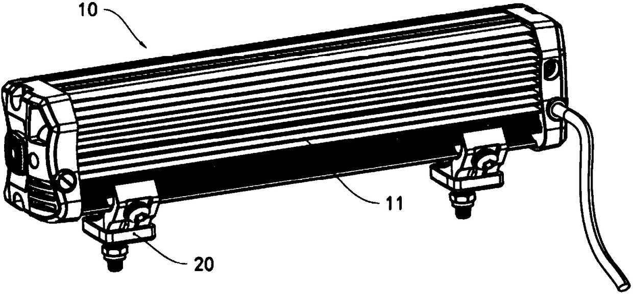
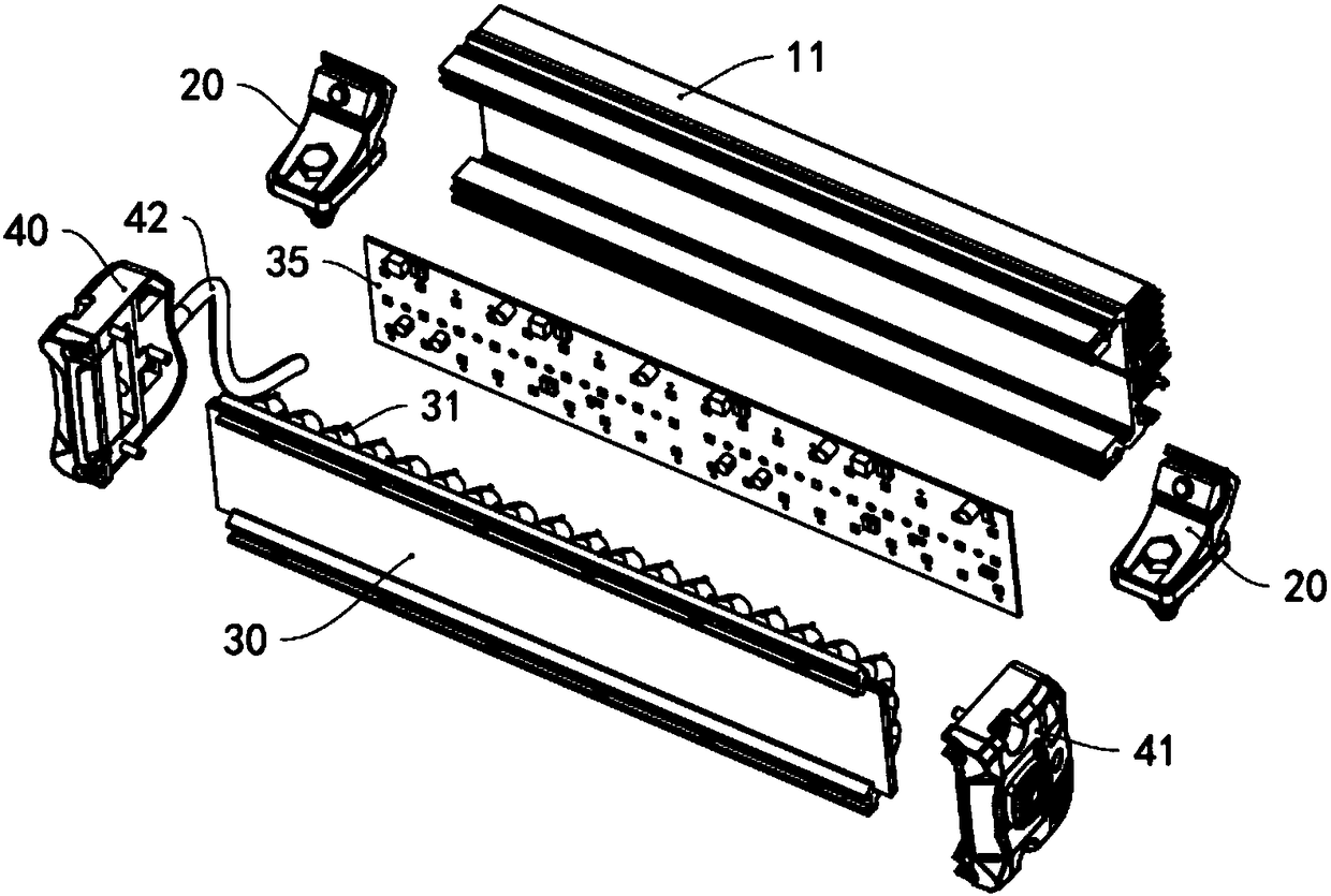
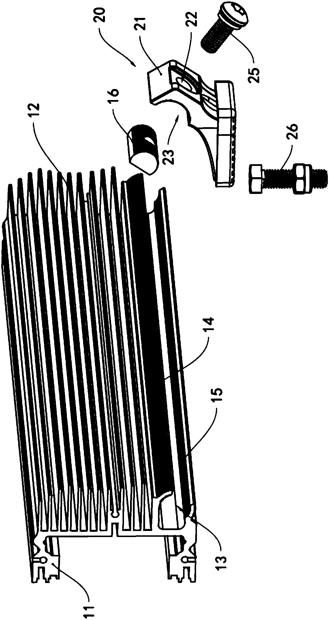
[0037] see figure 1In this embodiment, the LED lamp 10 has a heat sink 11 , and fixing components 20 are respectively arranged at both lateral ends of the heat sink 11 . see figure 2 , one side of the heat sink 11 is provided with a light-transmitting plate 30, and an aluminum-based printed circuit board 35 is arranged between the light-transmitting plate 30 and the heat sink 11; The device of a LED light-emitting chip and a power supply circuit, the power supply circuit can supply power to the LED light-emitting chip, so as to provide the electric energy needed for the LED light-emitting chip to emit light; the second side surface of the circuit board 35 is coated with thermal conductive silicone grease, thermal conductive silicone grease and radiator 11, to realize the th...


PUM


Abstract

The invention provides an LED lamp and a power circuit thereof. The power circuit comprises a driving chip and also comprises a temperature control circuit, wherein the driving chip is used for outputting a current to an LED light-emitting chip, an output end of the temperature control circuit is used for outputting an analogue voltage signal to a dimming pin of the driving chip, the temperature control circuit comprises a positive temperature coefficient thermistor and a negative temperature coefficient thermistor which are connected in series, a first end of the positive temperature coefficient thermistor is a high-level end, a second end of the positive temperature coefficient thermistor is connected with a first end of the negative temperature coefficient thermistor, a second end of the negative temperature coefficient thermistor is a low-level end, an output end of the negative temperature coefficient thermistor is connected with the second end of the positive temperature coefficient thermistor. The LED lamp is provided with the power circuit and the LED light-emitting chip. By the power circuit, the temperature of the LED lamp can be effectively controlled within a preset temperature range, excessively high temperature of a cooling shell of the LED light-emitting chip and the LED lamp is prevented, and the actual power of the LED lamp can be improved.

Description

technical field [0001] The invention relates to the field of LED lighting; more specifically, it relates to an LED lamp used in automobiles and a power supply circuit used in the LED lamp. Background technique [0002] At present, the lights of automobiles generally use halogen lamps or LED lights. Because LED light-emitting chips have the advantages of low power, high luminance, and long service life, the application of LED car lights is becoming more and more common. However, because the LED light-emitting chip will generate a lot of heat when it is working, if the heat is not removed in time, it will cause the accumulation of heat and affect the normal operation of the LED light-emitting chip, resulting in serious light decay, and even lead to the burning of the LED light-emitting chip. Therefore, the existing LED lamps all need to be provided with a radiator to guide away the heat generated by the LED light-emitting chip in time. [0003] However, if only a heat sink i...

Claims


Application Information

Patent Timeline
Patent Type & Authority Applications(China)
IPC IPC(8): H05B33/08G05D23/30H05B44/00
CPCG05D23/303H05B45/00
Inventor 李小鹏
Owner GUANGZHOU HANMA ELECTRONICS CO LTD
Why Eureka
Try Eureka