A homogeneous spiral plate fixed-bed reactor for gas-solid catalytic reaction

A technology of fixed bed reactor and fixed bed reaction, which is applied in chemical instruments and methods, chemical/physical processes, etc., can solve the problems of low utilization rate of catalyst bed space, difficulty in large-scale equipment, poor heat transfer effect, etc., and achieve High production capacity, less fouling and clogging, less floor space and less investment

Active Publication Date: 2021-02-02
QINGDAO UNIV OF SCI & TECH
View PDF7 Cites 0 Cited by
  • Summary
  • Abstract
  • Description
  • Claims
  • Application Information

AI Technical Summary

Problems solved by technology

[0007] In order to solve the technical problems of the existing shell-and-tube fixed bed reactor with poor heat transfer effect on the shell side, low space utilization rate of the catalyst bed, and difficulty in enlarging the device, the present invention provides A homogeneous spiral-plate fixed-bed reactor for gas-solid phase contact catalytic reaction

Method used


Image

  • A homogeneous spiral plate fixed-bed reactor for gas-solid catalytic reaction
  • A homogeneous spiral plate fixed-bed reactor for gas-solid catalytic reaction
  • A homogeneous spiral plate fixed-bed reactor for gas-solid catalytic reaction

Examples


Embodiment 1

[0030] 150,000 tons / year dimethyl oxalate (DMO) hydrogenation reactor

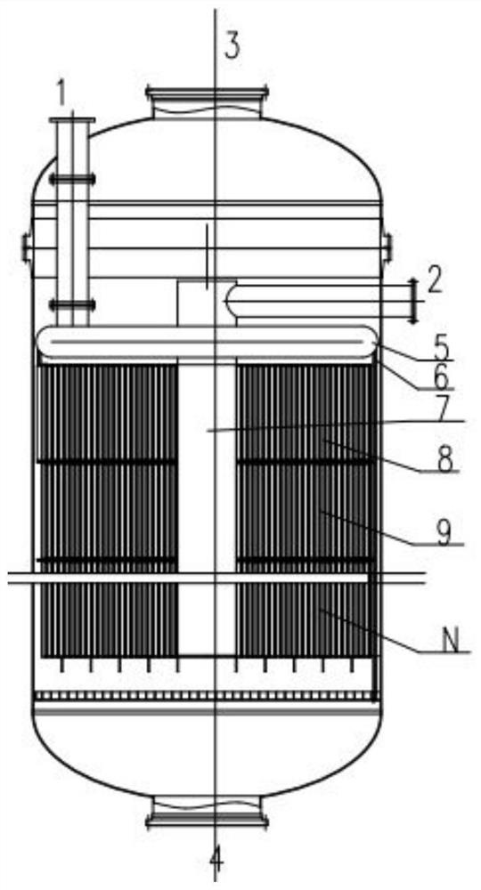
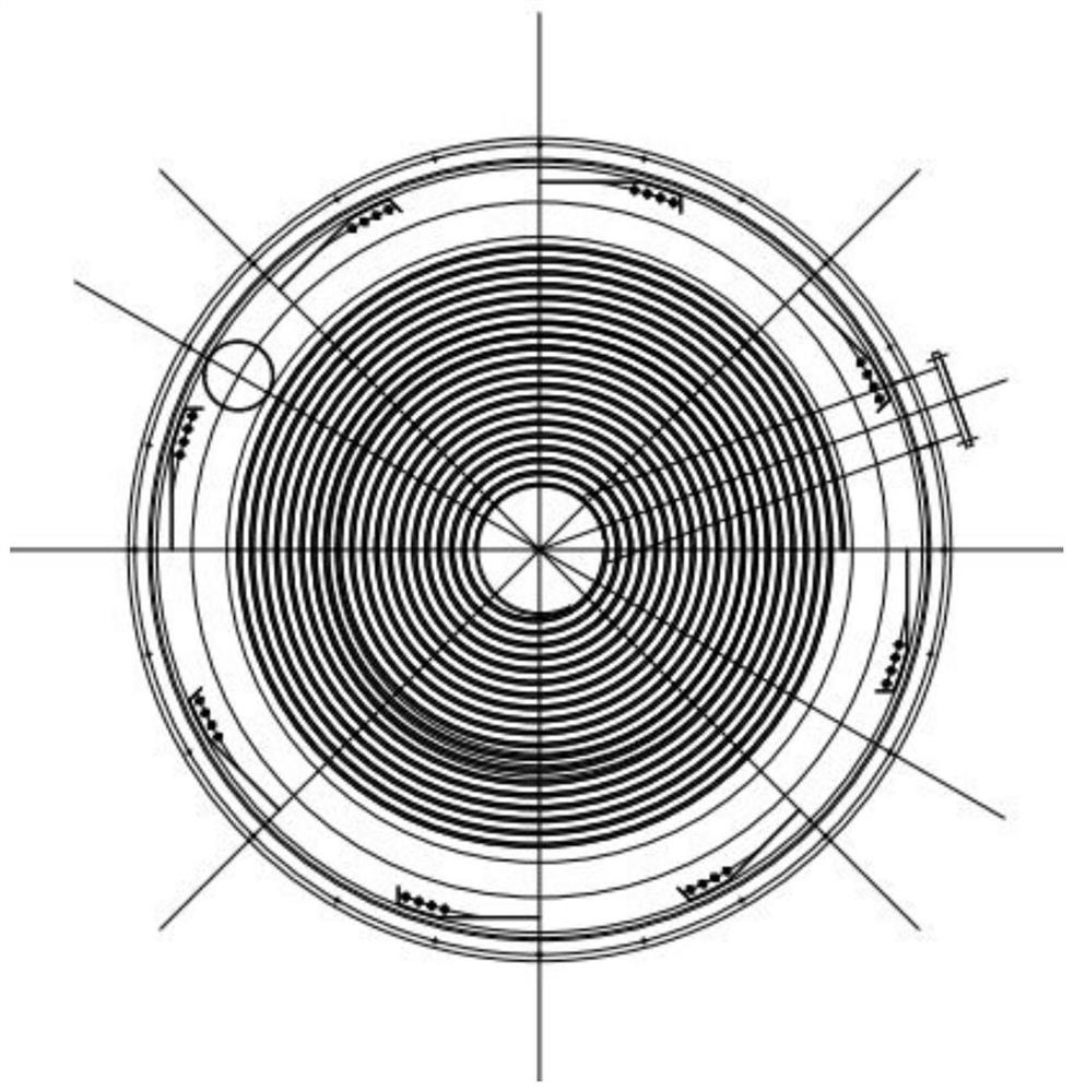
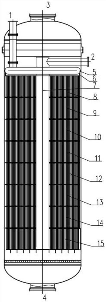
[0031] When the reactor of the present invention is used as a 150,000-ton / year DMO hydrogenation reactor, 8 sections of spiral plate reaction sections are required after calculation, and its structure is shown in image 3 with Figure 4 . The heat exchange medium inlet 1 is set on the top side of the reactor, and the outlet 2 is set on the upper side of the reactor. The gas enters the reactor from the top air inlet 3, passes through the catalyst fixed bed (8-15) to react, and leaves the reactor together with the product through the bottom gas outlet 4; the heat exchange medium passes through the annular pipe distributor 5 at the top of the reactor , distributed in proportion to the outer inlet of each spiral plate reaction section (08-15) by a number of distribution pipes 6, the heat is exchanged by the heat exchange medium channel spirally, and after the central pipe 7 entering the center of the reactio...

Embodiment 2

[0037] 35,000 tons / year vinyl acetate synthesis reactor

[0038] When the reactor of the present invention is used as a 35,000-ton / year vinyl acetate synthesis reactor, 10 sections of spiral plate reaction sections are needed after accounting, and its structure is shown in Figure 5 with Image 6 . In order to further enhance the heat exchange effect, a heat exchange medium is installed in each spiral plate reaction section to realize segmental temperature control, specifically: the heat exchange medium inlets 2 and 5-1 (medium temperatures can be the same or different) are set at The lower part of the spiral plate reaction section is connected to the outside of the heat exchange medium channel inside the reaction section. The heat exchange medium is spirally exchanged by the heat exchange medium channel. After entering the central tube 6-1 in the center of the reaction section, it flows out from the heat exchange medium outlet 1. The gas enters the reactor through the top g...


PUM


Abstract

The invention relates to a homogeneous spiral-plate fixed-bed reactor for gas-solid contact catalytic reaction, which includes gas phase and heat exchange medium inlet and outlet, and one or more spiral-plate fixed-bed reaction sections are arranged in the reactor. The advantages of the present invention: 1) significantly increase the shell-side heat transfer coefficient, increase the total heat transfer coefficient, strengthen the heat transfer effect, and reduce the heat transfer temperature difference; 2) the heat transfer distance and heat transfer area can be flexibly controlled, It is beneficial to the uniformity and control of the reaction bed temperature; 3) The volume utilization rate is large (the maximum can reach more than 70%, and the maximum is about 40% for the shell-and-tube reactor), and the production capacity of a single set of equipment is high, and the floor area and investment are significantly reduced ; 4) The heat exchange medium channel has a self-cleaning effect, and is not easy to generate dirt and blockage.

Description

technical field [0001] The invention relates to a fixed-bed reactor, in particular to a homogeneous spiral-plate fixed-bed reactor for gas-solid catalytic reaction. Background technique [0002] Fixed bed catalytic reactors are widely used in chemical industry and petroleum industry. [0003] The advantages of the fixed bed reactor are: ① small back mixing, effective contact between the fluid and the catalyst, and high selectivity when the reaction is accompanied by series side reactions; ② small mechanical loss of the catalyst; ③ simple structure. Its disadvantages are: ①The heat transfer effect of the shell side is poor, especially for strong exothermic reactions, it is prone to runaway temperature (the reaction temperature is out of control, rises sharply, exceeding the allowable range); ②The catalyst cannot be replaced during operation, and the catalyst needs to be frequently regenerated The reaction is generally not suitable for use, and it is often replaced by a fluid...

Claims


Application Information

Patent Timeline
Patent Type & Authority Patents(China)
IPC IPC(8): B01J8/04
CPCB01J8/0465B01J8/0469B01J8/0496B01J2208/00132
Inventor 李建隆董纪鹏陈光辉范军领王伟文
Owner QINGDAO UNIV OF SCI & TECH
Why Eureka
Try Eureka