Al technical title is built by PatSnap Al team. It summarizes the technical point description of the patent document.
A pipe cutting machine and hydraulic technology, applied in the field of hydraulic pipe cutting machines, can solve the problems of unstable clamping, complex overall structure, unclean incision, etc., to reduce subsequent processing procedures, simple device structure, and reduce negative effects. Effect
Inactive Publication Date: 2018-06-05
丹阳市超宇五金磨具有限公司
View PDF4 Cites 1 Cited by
Summary
Abstract
Description
Claims
Application Information
AI Technical Summary
This helps you quickly interpret patents by identifying the three key elements:
Problems solved by technology
Method used
Benefits of technology
Problems solved by technology
[0002] With the development and progress of industry, steel pipe has become an indispensable important product and raw material in industrial production, and is widely used in petroleum, chemical, electric power, natural gas, metallurgy, shipbuilding, boiler, pharmaceutical, water treatment and other industries, as well as pipeline installation of new projects Engineering, pipeline maintenance and other related technical fields, there are many related equipment for steel pipe cutting in the prior art, such as planetary cutting machine, hydraulic cutting machine, external card cutting machine, numerical control hydraulic cutting machine, electric cutting machine, pneumatic cutting machine Machines, etc., hydraulic cutting equipment is the most widely used, but the cutting equipment related to the existing technology generally has the following technical problems, 1) the overall structure is complex, the operation is troublesome, and the clamping is unstable; 2) the scope of use is narrow and can only be used for Cutting one or two steel pipes greatly limits the scope of use of the cutting device, and the feeding accuracy is low; 3) Most of the existing cutting equipment is only simple cutting, and the groove cannot be processed, so that the incision is prone to deformation, and the incision is not smooth. Clean, poor finish
Method used
Image
Click on the blue label to locate the original text in one second.
Reading with bidirectional positioning of images and text.
Examples
Embodiment Construction
[0011] The technical solutions in the embodiments of the present invention will be clearly and completely described below in conjunction with the accompanying drawings in the embodiments of the present invention. Obviously, the described embodiments are only part of the embodiments of the present invention, not all of them. Based on the embodiments of the present invention, all other embodiments obtained by persons of ordinary skill in the art without making creative efforts belong to the protection scope of the present invention.
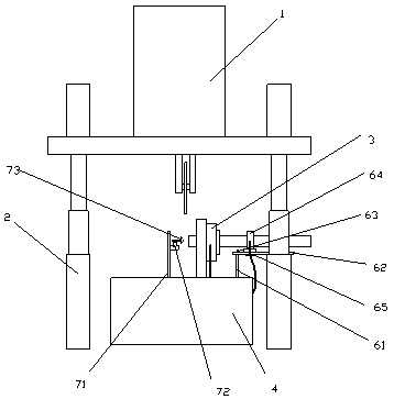
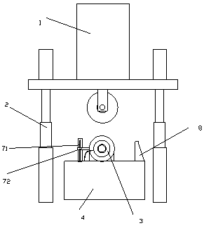
[0012] A hydraulic pipe cutter, comprising a cutting machine head 1, a hydraulic cutting support 2, a pneumatic positioning chuck 3, a feeding mechanism, a deburring mechanism and a pressure detection system, the hydraulic cutting support is a multi-stage hydraulic telescopic rod, and the hydraulic cutting The bottom of the support is provided with a cutting table 4, and the bottom of the cutting table is provided with a hydraulic cylinder and a pne...
PUM
Abstract
The invention discloses a hydraulic pipe cutter which comprises a cutter head, a hydraulic cutting bracket, a pneumatic positioning chuck, a feeding mechanism, a deburring mechanism and a pressure detection system, wherein the hydraulic cutting bracket adopts a multi-stage hydraulic telescopic pole; a cutting table is arranged at the bottom of the hydraulic cutting bracket; a hydraulic cylinder and a pneumatic cylinder, which are connected with the multi-stage hydraulic telescopic pole, are arranged at the bottom of the cutting table; and the cutter head is fixedly hung at the top of the hydraulic cutting bracket. The device structure is simple, and the equipment cost is low; a vertical up-down cutting way is adopted, and the cutting is performed by self gravity of the cutter head; a pressure sensor and a display facilitate reducing negative effects in the cutting process; by the adoption of a travel switch and a feeding pneumatic chuck, error accumulation caused by complicated transmission links is avoided, and the machining precision is improved; and after cutting is completed, the deburring mechanism is used for polishing a fracture to reduce the subsequent manufacturing procedure.
Description
technical field [0001] The invention relates to a pipe material cutting device, in particular to a hydraulic pipe cutting machine. Background technique [0002] With the development and progress of industry, steel pipe has become an indispensable important product and raw material in industrial production, and is widely used in petroleum, chemical, electric power, natural gas, metallurgy, shipbuilding, boiler, pharmaceutical, water treatment and other industries, as well as pipeline installation of new projects Engineering, pipeline maintenance and other related technical fields, there are many related equipment for steel pipe cutting in the prior art, such as planetary cutting machine, hydraulic cutting machine, external card cutting machine, numerical control hydraulic cutting machine, electric cutting machine, pneumatic cutting machine Machines, etc., hydraulic cutting equipment is the most widely used, but the cutting equipment related to the existing technology generall...
Claims
Application Information
Patent Timeline
Application Date:The date an application was filed.
Publication Date:The date a patent or application was officially published.
First Publication Date:The earliest publication date of a patent with the same application number.
Issue Date:Publication date of the patent grant document.
PCT Entry Date:The Entry date of PCT National Phase.
Estimated Expiry Date:The statutory expiry date of a patent right according to the Patent Law, and it is the longest term of protection that the patent right can achieve without the termination of the patent right due to other reasons(Term extension factor has been taken into account ).
Invalid Date:Actual expiry date is based on effective date or publication date of legal transaction data of invalid patent.