

Flexible circuit board welding device
A technology of flexible circuit boards and welding devices, which is applied to welding positions, auxiliary devices, printed circuits, etc., can solve problems such as high temperature and easy burns to workers, and achieve the effects of shortening the interval time, avoiding burns, and improving processing efficiency
Inactive Publication Date: 2018-06-05
宁波隆锐机械制造有限公司
View PDF0 Cites 11 Cited by
- Summary
- Abstract
- Description
- Claims
- Application Information
AI Technical Summary
Problems solved by technology
Secondly, the temperature of the support plate is high after use, and it is easy to burn the workers
Method used
View moreImage
Smart ImageViewing Examples

Examples
Embodiment Construction
[0023] Below in conjunction with accompanying drawing and specific embodiment the present invention will be described in further detail:
Login to View More PUM
 Abstract
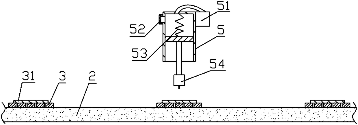
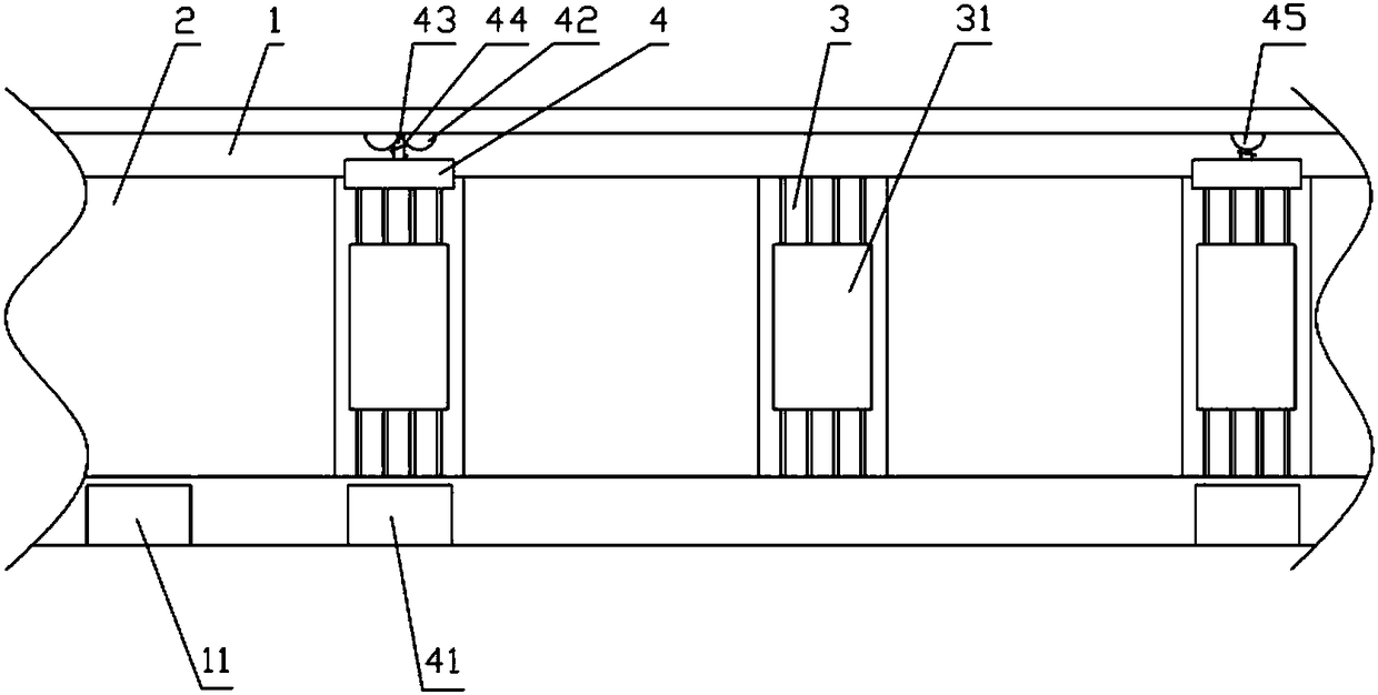
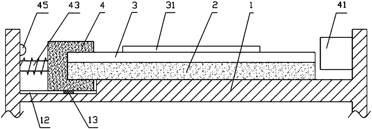
The invention relates to the field of circuit board production, and particularly discloses a flexible circuit board welding device comprising a machine frame, a cooling fan, a conveyor belt, a weldingmechanism and a control mechanism, wherein a supporting plate is fixed on the conveyor belt; the welding mechanism comprises an electric soldering iron, a cylinder and a welding fan; the cylinder isprovided with an exhaust port, and a returning spring is arranged in the cylinder; the control mechanism includes a stopping mechanism and a cooling mechanism, and the stopping mechanism and the cooling mechanism each include a cooling fan and an air bag, the air bag and the cooling fan are located on both sides of the conveyor belt respectively, the cooling fan is fixed on the machine frame, andthe air bag can slide relative to the machine frame. A first heated expansive substance is stored in the air bag of the stopping mechanism, a second heated expansive substance is stored in the air bagof the cooling mechanism, a closing switch is fixed on the machine frame, and the closing switch can shut down the conveyor belt and the welding fan, and the machine frame is provided with a compression spring. According to the scheme, the supporting plate can be cooled while a circuit board is welded.
Description
technical field [0001] The invention relates to the field of circuit board production, in particular to the field of flexible circuit board production. Background technique [0002] Circuit board, also known as printed circuit board, can gather a large number of electrical components together and provide them with electrical connections, and is an essential part of electronic components. The flexible circuit board is a kind of circuit board, which is a highly reliable and excellent flexible circuit board made of polyimide or polyester film as the base material. It is mainly used in many products such as mobile phones, notebook computers, PDAs, digital cameras, and LCMs. [0003] During the production process of the flexible circuit board, the circuit board needs to be soldered. When welding, a support plate needs to be installed under the circuit board. The support plate supports the circuit board and the electric soldering iron to prevent the electric soldering iron from e...
Claims
Login to View More Application Information
Patent Timeline
 Patent Type & AuthorityApplications(China)
IPC IPC(8): B23K3/02B23K3/08B23K37/047B23K101/42
CPCB23K3/087B23K3/026B23K3/085B23K37/047
Inventor王健
Owner宁波隆锐机械制造有限公司