Integrated heat pipe heat dissipation device

A cooling device and an integrated technology, applied in the field of heat transfer, can solve the problems that the life of the heat pipe system is easy to cause risks, the problem of corrosion protection cannot be completely solved, and the reliability of the heat pipe system is reduced, so as to shorten the flow path of the boundary layer flow and enhance the air quality. Effect of permeable, high-efficiency heat transfer surfaces

Inactive Publication Date: 2018-06-05
陈庆山
View PDF3 Cites 0 Cited by
  • Summary
  • Abstract
  • Description
  • Claims
  • Application Information

AI Technical Summary

Problems solved by technology

The cast iron type is corrosion-resistant, but its surface is rough, heavy, low thermal efficiency, high energy consumption and environmental pollution in the production process; the aluminum type has high thermal efficiency, but its corrosion resistance is poor and its life is short; steel heat dissipation The performance is good, but its biggest problem is that it is prone to corrosion and leakage. At present, the internal anti-corrosion measures adopted by the manufacturer still have many problems in terms of process guarantee, so that the anti-corrosion problem cannot be completely solved, and the large-scale use of preservatives will also pollute the environment; copper The thermal efficiency of the aluminum composite type is high, and the corrosion resistance of the copper tube is good, but the price of copper is expensive, which is a burden on the manufacturer and the user; the other type is the heat pipe type convection formed by using a "U"-shaped tube to penetrate the fin and expand it. The radiator has high thermal efficiency, but it needs to be welded and sealed with a small "U" elbow to form an integrally connected heat conduction pipeline. There are too many welding ports of the heat conduction pipe, and more small "U" elbow welding ports The reliability of the overall circuit heat pipe system is reduced, the life of the heat pipe system is likely to cause risks, and the welding volume is large and the manufacturing process is complicated

Method used


Image

  • Integrated heat pipe heat dissipation device
  • Integrated heat pipe heat dissipation device
  • Integrated heat pipe heat dissipation device

Examples


Embodiment Construction

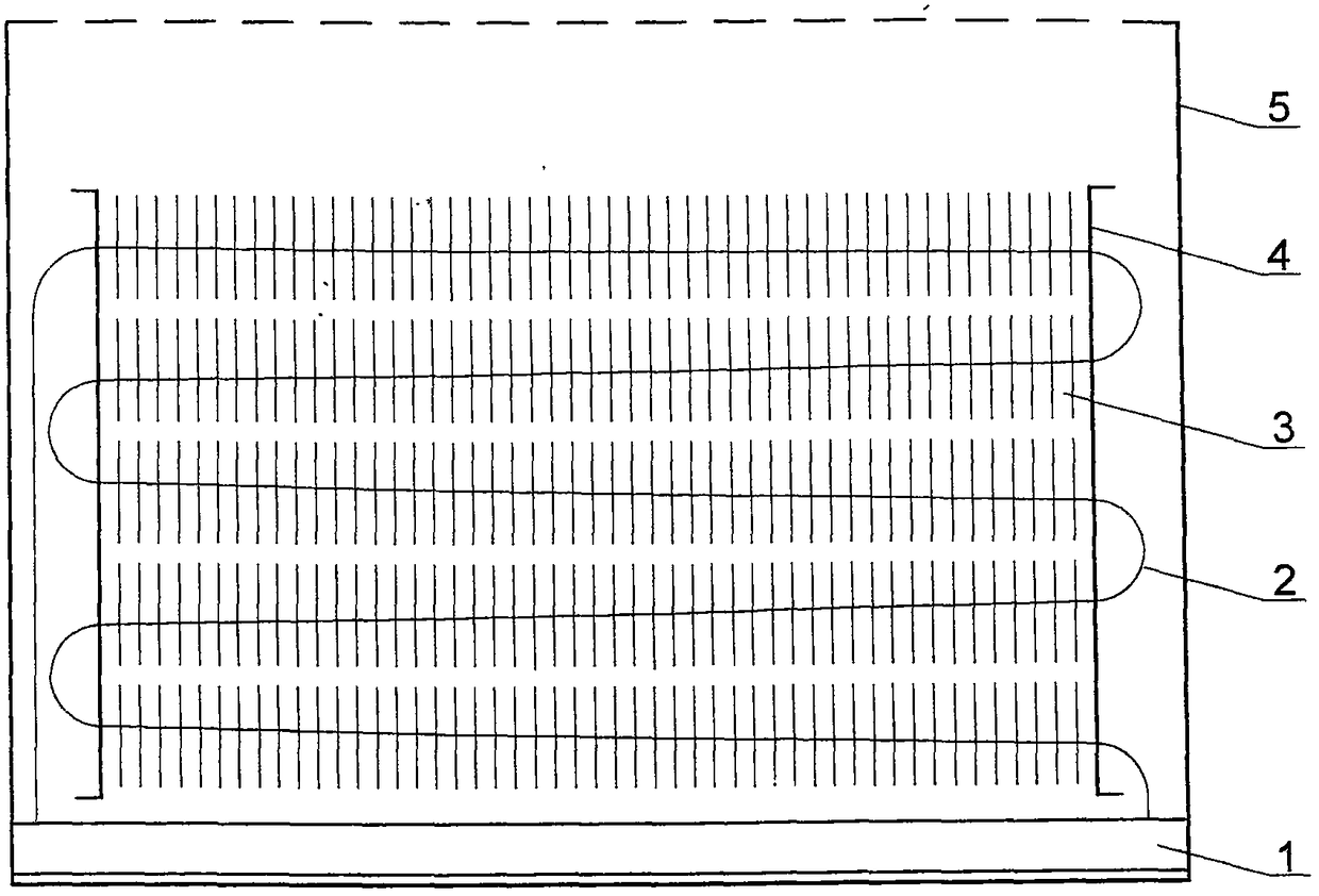
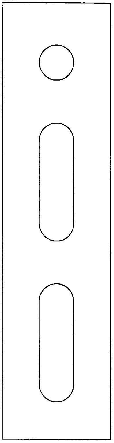
[0024] Such as figure 1 As shown, an integrated heat pipe cooling device provided by the present invention includes: an evaporator (1), a heat pipe (2), a cooling fin (3), a fixed end plate (4) and an outer cover (5); the heat pipe (2) It is made by bending the whole continuous pipe through a loop, and there is a certain angle between the transverse axis of the heat pipe and the horizontal direction. The cooling fins (3) are small rectangular fins, which are tightly fixed on the heat conducting pipes (2) through expansion tubes. The fixed end plate (4) is installed on the curved end of the heat pipe (2), parallel to the heat dissipation fins (3), and is used for assembling and forming the heat dissipation inner core and installing and fixing the outer cover.

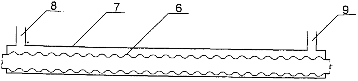
[0025] Such as figure 2 or figure 1 As shown: the evaporator is composed of a sealed cavity composed of a heat source tube (6) and an evaporator shell (7). The evaporator shell (7) is provided with a steam outlet (8)...


PUM


Abstract

The invention provides an integrated heat pipe heat dissipation device. The integrated heat pipe heat dissipation device comprises an evaporator (1), a heat conduction pipe (2), cooling fins (3), fixing end plates (4) and an outer cover (5). The integrated heat pipe heat dissipation device is characterized in that the heat conduction pipe (2) is formed by bending a whole continuous pipe in a loopmanner, and a certain included angle exists between the axis of the heat conduction pipe and the horizontal direction. The integrated heat pipe heat dissipation device is good in anti-corrosion performance, high in heat dissipation efficiency, large in safety margin and long in service life and has the beneficial effects of being small in weight, low in cost, capable of saving water, materials andenergy, environmentally friendly and the like.

Description

technical field [0001] The invention relates to the field of heat transfer, in particular to an integrated heat pipe cooling device. Background technique [0002] At present, the heating and cooling devices seen on the market are made of cast iron, steel, aluminum, copper-aluminum composite, and heat pipe convective radiators formed by compression after the fins are pierced by "U" type tubes. The cast iron type is corrosion-resistant, but its surface is rough, heavy, low thermal efficiency, high energy consumption and environmental pollution in the production process; the aluminum type has high thermal efficiency, but its corrosion resistance is poor and its life is short; steel heat dissipation The performance is good, but its biggest problem is that it is prone to corrosion and leakage. At present, there are still many problems in the process guarantee of the internal anti-corrosion measures adopted by the manufacturer, so that the anti-corrosion problem cannot be complete...

Claims


Application Information

Patent Timeline
Patent Type & Authority Applications(China)
IPC IPC(8): F28D15/02F25B39/02F28F1/12F28F19/00F28F21/08
CPCF25B39/02F28D15/02F28F1/124F28F19/00F28F21/085
Inventor 陈庆山孙鸿超董晓丽
Owner 陈庆山
Why Eureka
Try Eureka