
A dual-frequency feed horn including a metal ring

A feed horn, metal ring technology, applied to waveguide horns, devices that make antennas work in different bands at the same time, antennas, etc., can solve the problems of high operation and maintenance requirements, large equipment volume, etc. Transmission characteristics, saving processing costs, and the effect of good impedance matching

Active Publication Date: 2020-03-17
ANHUI SUN CREATE ELECTRONICS
View PDF7 Cites 0 Cited by
  • Summary
  • Abstract
  • Description
  • Claims
  • Application Information

AI Technical Summary

Problems solved by technology

The biggest problem with this method is that it is difficult to ensure that the two radars detect the same target, and the amount of equipment is large, and the operation and maintenance requirements are high.

Method used


Image

  • A dual-frequency feed horn including a metal ring
  • A dual-frequency feed horn including a metal ring
  • A dual-frequency feed horn including a metal ring

Examples


Embodiment 1

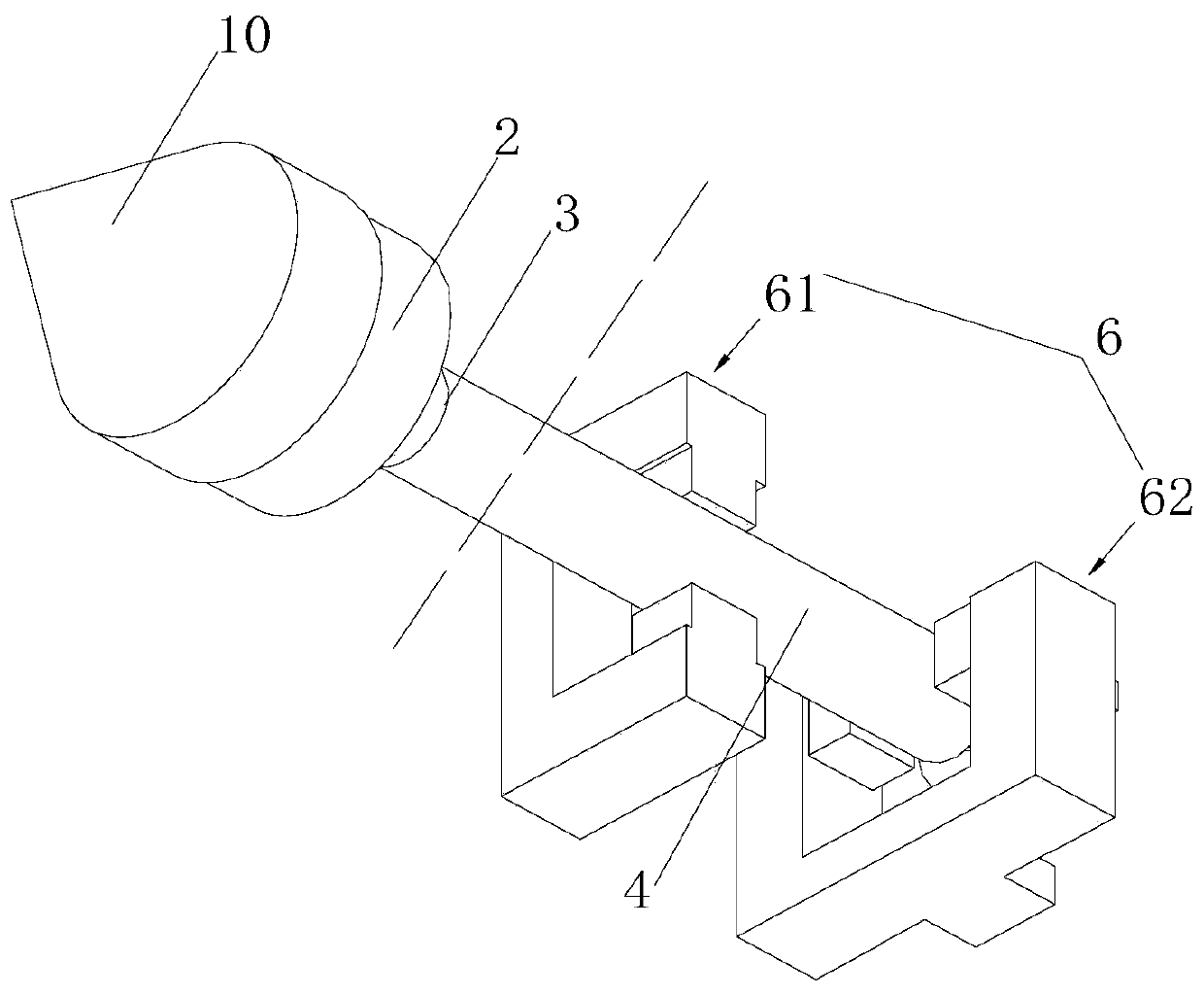
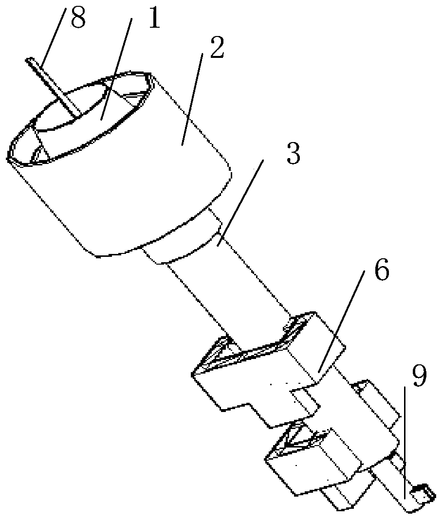
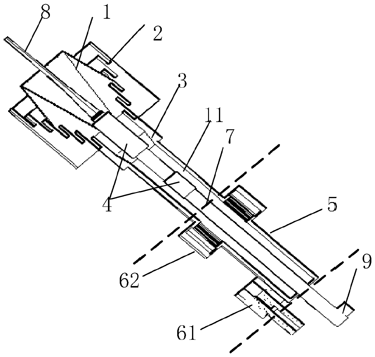
[0047] Such as Figure 1-4 As shown, a dual-frequency feed horn including a metal ring includes a first frequency band feed horn, a metal ring 4 for impedance matching, a second frequency band dielectric rod 8, a second frequency band circular waveguide 7, and a second frequency band positive Cross mode 9. The first band feed horn includes a first band vertical corrugated horn 2 as a radiating section 83, a first band variable diameter section 3 as an opening angle section, a first band waveguide transition section 5, and a first band waveguide transition section arranged in sequence An incentive structure 6 is also provided on 5.

[0048] The second frequency band circular waveguide 7 is coaxially arranged in the first frequency band feed horn. The signals of the first frequency band pass through the second frequency band formed between the outer surface of the second frequency band circular waveguide 7 and the cavity sidewall of the first frequency band feed horn. A cavity 11...

Embodiment 2

[0065] The difference from Embodiment 1 is that the included angle range between the first frequency band reducing section 3 and the central axis of the dual-frequency feed horn is 0°.

Embodiment 3

[0067] The difference from Embodiment 1 is that the included angle range between the first frequency band reducing section 3 and the central axis of the dual-frequency feed horn is 10°.


PUM


Abstract

The invention discloses a dual-frequency feed horn including a metal ring, which includes a first frequency band feed horn, a second frequency band circular waveguide, and a metal ring for impedance matching. The first frequency band is lower than the second frequency band, and the second frequency band The circular waveguide is coaxially arranged in the cavity of the first frequency band feed horn, and the signal of the first frequency band passes through the first cavity formed between the outer surface of the second frequency band circular waveguide and the cavity side wall of the first frequency band feed horn Body transmission, the signal of the second frequency band is transmitted through the inner cavity of the circular waveguide of the second frequency band; the metal ring is coaxially arranged in the first cavity for transmitting the signal of the first frequency band. The advantage of this invention is that: since the feed speakers have different index requirements, in the coaxial feed technical solution, the first cavity realizes the effective radiation of electromagnetic waves in the first frequency band, and the circular waveguide in the second frequency band realizes the effective radiation of electromagnetic waves in the second frequency band. The innovative loading metal ring in the first cavity achieves good impedance matching, thus meeting the different index requirements of the feed speaker.

Description

Technical field [0001] The technical field of the radar antenna of the present invention, in particular, is a dual-frequency feed horn including a metal ring. Background technique [0002] The dual-band dual-polarization radar helps to further understand the refined physical structure and evolution characteristics of the weather system from clear sky atmosphere → cloud and precipitationprecipitation, and improve our understanding of the physical mechanism of weather system development. Through continuous observation of various weather phenomena such as non-precipitation, weak precipitation clouds and stratified, convective (thunderstorm) precipitation, fog, haze, etc., all-weather, all-sky, high-temporal-spatial resolution, multi-parameter continuous observations to obtain meteorological targets such as clouds and precipitation Time and space distribution of macro and micro physical parameters. It will not only promote the in-depth development of small and medium-scale weathe...

Claims


Application Information

Patent Timeline
Patent Type & Authority Patents(China)
IPC IPC(8): H01Q1/36H01Q1/50H01Q1/52H01Q5/307H01Q13/02H01Q15/24
CPCH01Q1/36H01Q1/50H01Q1/521H01Q13/02H01Q15/24H01Q5/307
Inventor 李运志孙浩赵继明金秀梅
Owner ANHUI SUN CREATE ELECTRONICS
Learn More