
X-waveband dielectric horn antenna

A horn antenna and X-band technology, applied in the field of antennas, can solve the problems of increased workload and cost, large envelope size, waste, etc., and achieve the effect of reduced production workload, small impact on processing technology, and mature processing technology

Inactive Publication Date: 2018-06-08
SHANGHAI AEROSPACE ELECTRONICS CO LTD +1
View PDF6 Cites 2 Cited by
  • Summary
  • Abstract
  • Description
  • Claims
  • Application Information

AI Technical Summary

Problems solved by technology

However, as a common antenna for satellite communication platforms, microstrip antennas still have certain disadvantages
The operating frequency band of the microstrip antenna is narrow, and its relative bandwidth is only 1%~7%. Especially for the circularly polarized microstrip antenna, the axis ratio bandwidth that meets the application requirements is narrower, and it cannot be applied to some broadband systems.
In addition, due to errors in processing, in order to make the microstrip antenna meet the requirements of the working frequency band, the performance of the actually processed microstrip patch is usually explored and adjusted many times, especially for the microstrip antenna in the X-band or higher frequency bands. Antenna design, especially for large arrays, undoubtedly adds a huge workload and cost
Furthermore, the microstrip antenna array usually adopts the overall processing and installation method of the array. If the antenna unit fails and needs to be replaced, the entire array needs to be replaced, resulting in waste.
The helical antenna is also often used in the X-band spaceborne antenna system. Although it has a wide operating bandwidth and good circular polarization performance, its envelope size is generally large, and its height even reaches 3 times the operating wavelength, which will occupy Satellite space installation resources, not to mention array antennas

Method used


Image

  • X-waveband dielectric horn antenna
  • X-waveband dielectric horn antenna
  • X-waveband dielectric horn antenna

Examples


Embodiment Construction

[0023] The specific implementation manners of the present invention will be further described in detail below in conjunction with the accompanying drawings.

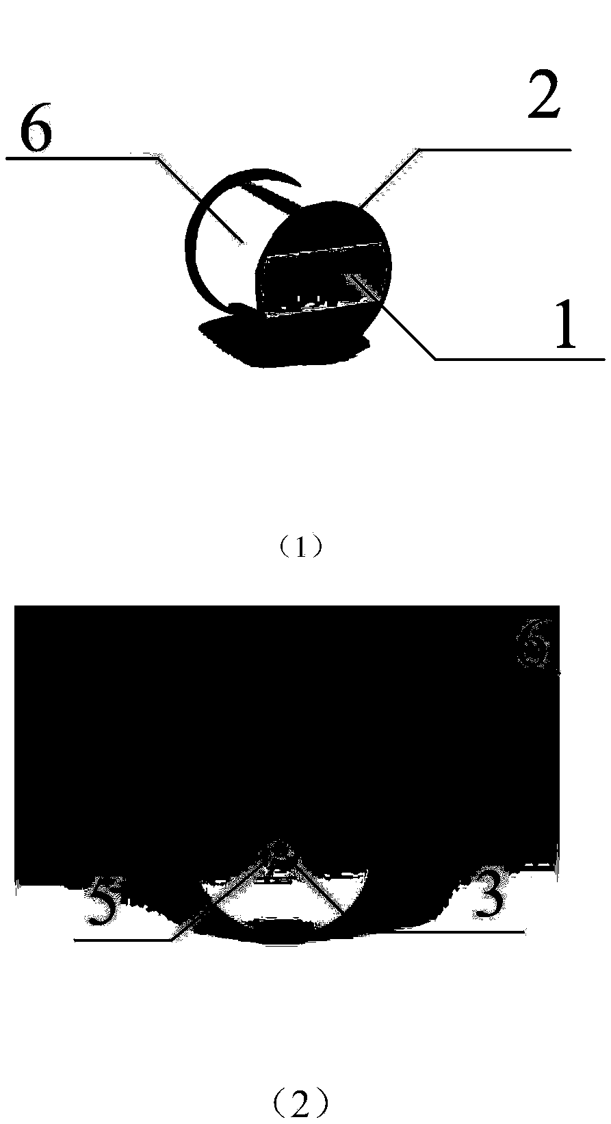
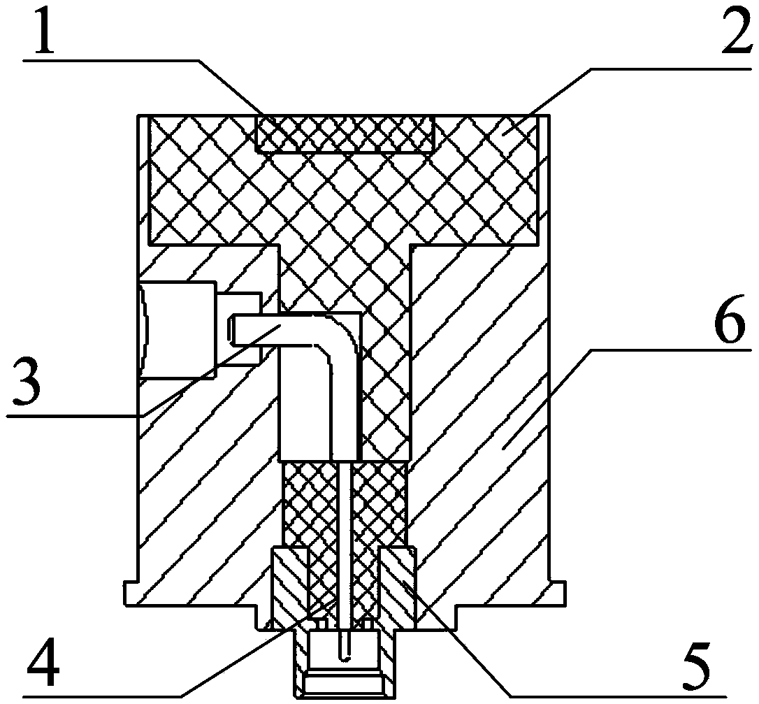
[0024] The X-band dielectric horn antenna proposed by the present invention is suitable for X-band satellite-borne antenna systems or large-scale phased array antennas to receive or send signals to concerned targets or areas. Such as figure 1 Shown is the schematic diagram of the three-dimensional structure of the present invention, figure 2 Shown is the sectional view of the present invention, in conjunction with figure 1 (1), (2) and figure 2 , The X-band dielectric horn antenna of the present invention mainly includes a polarizer 1 , a filling medium 2 , an inverted L-shaped probe 3 , a core sleeve 4 , a feed structure 5 and a metal shell 6 .

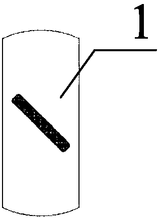
[0025] The polarizer 1 is a Rogers4533 printed board with a thickness of 1.524mm, and the shape of the polarizer is cut from a circular piece. One side of the polarizing ...


PUM


Abstract

The invention provides an X-waveband dielectric horn antenna. The X-waveband dielectric horn antenna comprises a polarized sheet, filling dielectric, an inverted L-shaped probe, a core sleeve, a feedstructure and a metal shell; the polarized sheet is fixed in a groove in the top of the filling dielectric, and the top of the polarized sheet is flush with the top of the filling dielectric; a ''horizontal-line''-shaped slit is dig in a rectangular structure at the lower end of the filling dielectric, and the inverted L-shaped probe is placed in the slit; the core sleeve is hollow cylindrical dielectric and arranged on the exterior of the inverted L-shaped probe in a sleeving manner, wherein the top end of the core sleeve is flush with the bottom of the filling dielectric; the feed structureis a cylindrical metal shell and has a hollow stage-shaped interior, wherein the upper end of the feed structure and the relatively thin part at the lower end of the core sleeve are tightly matched while the bottom of the feed structure and the thinnest part of the inverted L-shaped probe jointly form a feed port; the polarized sheet, the filling dielectric, the inverted L-shaped probe, the core sleeve and the feed structure are all placed in the metal shell; the filling dielectric, the core sleeve and the interior of the metal shell are tightly matched; and the inverted L-shaped probe and themetal shell are concentric, and the probe can perform feed through the bottom.

Description

technical field [0001] The invention belongs to the technical field of antennas, and is mainly used in an X-band space-borne antenna system or a large phased array antenna to receive or send signals to a concerned target or area. Background technique [0002] In deep space communication, the signal received and transmitted by the satellite antenna system is often transmitted in the form of electromagnetic waves, and the role played by the antenna is very important. With the rapid development of space-borne antennas, the performance requirements for multi-function, multi-band, long-distance, and high-power antennas are getting higher and higher. The satellite-based phased array antenna has the characteristics of high gain, long range, fast beam scanning, fast beam deformation, and multiple beams, which meet the performance requirements of satellite communication system equipment and are used more and more widely. [0003] The antennas of satellite communication systems usual...

Claims


Application Information

Patent Timeline
Patent Type & Authority Applications(China)
IPC IPC(8): H01Q13/02H01Q15/24H01Q1/50
CPCH01Q1/50H01Q13/0241H01Q15/24
Inventor 蒋琪鲍远顶段耀铎何旺辛文莉
Owner SHANGHAI AEROSPACE ELECTRONICS CO LTD
Learn More