Supercritical mixed working medium steam turbine exhaust gas separation system and pumping method

A technology of mixing working fluids and steam turbines, which is applied in steam engine devices, mechanical equipment, engine components, etc., can solve the problems that the suction system is difficult to meet the requirements, achieve a higher boost ratio, and improve the utilization rate of water resources, pumping The effect of large suction flow and high boost ratio

Inactive Publication Date: 2018-06-12
XI AN JIAOTONG UNIV
View PDF4 Cites 4 Cited by
  • Summary
  • Abstract
  • Description
  • Claims
  • Application Information

AI Technical Summary

Problems solved by technology

However, the content of carbon dioxide in the exhaust gas of a supercritical mixed working medium steam turbine can reach 8%-10% of the total gas composition, which is much higher than the content of non-condensable gas in the exhaust gas of a conve

Method used


Image

  • Supercritical mixed working medium steam turbine exhaust gas separation system and pumping method
  • Supercritical mixed working medium steam turbine exhaust gas separation system and pumping method
  • Supercritical mixed working medium steam turbine exhaust gas separation system and pumping method

Examples


Embodiment 1

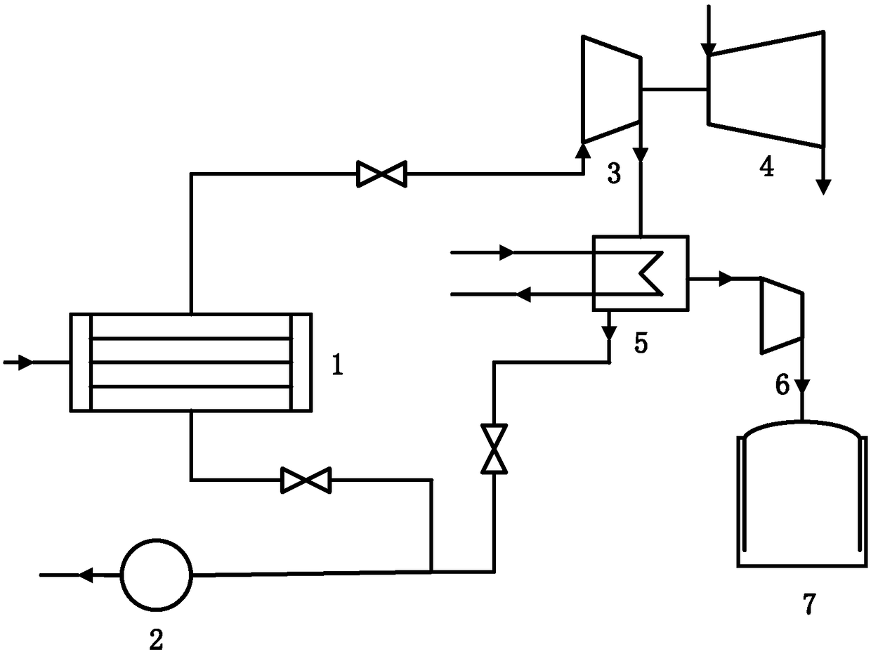
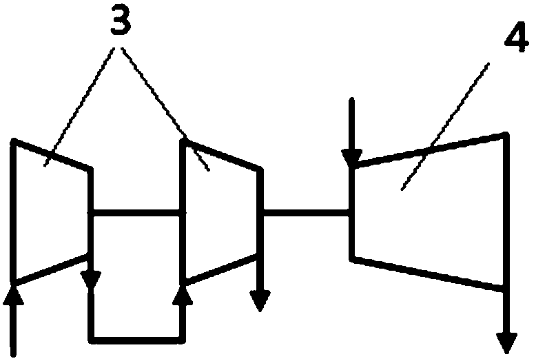
[0044] The inlet of the condenser 1 is connected to the outlet of the steam turbine, the liquid outlet of the condenser 1 is connected to the water pump 2, the gas outlet of the condenser 1 is connected to the inlet of the first centrifugal compressor through a pipeline, and the outlet of the first centrifugal compressor The inlet of the second centrifugal compressor is connected by a pipeline, and the outlet of the second centrifugal compressor is connected with the inlet of the steam-water separator 5 by a pipeline, and the second centrifugal compressor is connected with the centripetal turbine 4 by a speed changer; The gas outlet is connected to the inlet of the gas compression device 6 through a pipeline, the liquid outlet of the steam-water separator 5 is connected to the water pump 2 through a pipeline, the outlet of the gas compression device 6 is connected to the storage tank 7, the water pump 2 is connected to the feed water heater, and the feed water heater Connect wi...

Embodiment 2

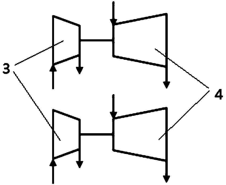
[0047] The difference from Embodiment 1 is that the first centrifugal compressor and the first centrifugal compressor are connected in parallel, respectively driven by two centripetal turbines 4; the inlets of the first centrifugal compressor and the second centrifugal compressor are respectively connected to the The gas outlet of the condenser 1 is connected, the outlets of the first centrifugal compressor and the second centrifugal compressor are connected with the inlet of the steam-water separator 5 through pipelines, and two centripetal turbines 4 drive the first centrifugal compressor and the second centrifugal compressor respectively. The centrifugal compressor works, and the rest of the structure is the same.

[0048] In Embodiment 1, the first centrifugal compressor and the second centrifugal compressor are connected in series, which is equivalent to two-stage compression, so as to increase the boosting ratio. In the second embodiment, the first centrifugal compressor...


PUM


Abstract

The invention discloses a supercritical mixed working medium steam turbine exhaust gas separation system. The pumping system is connected with a steam turbine and comprises a condenser, at least one centrifugal compressor, a driving device, a separation device and a storage tank, wherein the condenser is connected with an outlet of the steam turbine; the condenser conducts primary separation on mixed gas discharged by the steam turbine; a gas outlet of the condenser is connected with an inlet of the centrifugal compressor; the driving device is used for driving the centrifugal compressor to operate; an outlet of the centrifugal compressor is connected with the separation device; the separation device is used for conducting secondary separation on the mixed gas; a gas outlet of the separation device is connected with the storage tank. The system conducts effective separation on the mixed gas in exhaust gas of the supercritical mixed working medium steam turbine. The system is high in efficiency, large in pumping flow and high in supercharging ratio. The problems existing in pumping, recovery, storage and utilization of noncondensable gases such as high-flow carbon dioxide in the exhaust gas of the supercritical mixed working medium steam turbine are solved effectively. Pollution of the carbon dioxide to the environment is avoided.

Description

【Technical field】 [0001] The invention relates to the field of power generation equipment, in particular to a suction system and a suction separation method for separating the exhaust gas of a mixed working medium steam turbine. 【Background technique】 [0002] my country's coal-based energy structure will not change in the short term. The traditional coal-fired power generation technology burns coal in the air to release heat, converts the chemical energy in the coal into thermal energy to heat the feed water, and generates water vapor to drive the steam turbine to generate power. . The conventional coal gasification technology utilizes the partial oxidation-gasification reaction of coal in the air to produce syngas. In the above two types of processes, the loss of coal energy quality is large, and a large amount of pollution products such as SOx, NOx and solid particles are produced at the same time, which aggravates the degree of air pollution and the cost of emission redu...

Claims


Application Information

Patent Timeline
IPC IPC(8): F01D25/32F01D25/00F01D15/10F01K25/10
CPCF01D25/32F01D15/10F01D25/00F01K25/103
Inventor 戴义平霍耀武王江峰赵攀夏文凯杨翼
Owner XI AN JIAOTONG UNIV
Why Eureka
Try Eureka