Preparation method of N type heterojunction two-sided solar battery

A solar cell and heterojunction technology, applied in the field of solar cells, can solve the problems affecting the development of N-type heterojunction double-sided cells, the increase of light absorption of P-type doped amorphous silicon layer, and the decrease of effective bandgap width. Achieve good surface passivation effect, good field passivation effect, and reduce uniformity requirements

Active Publication Date: 2018-06-15
青海黄河上游水电开发有限责任公司西宁太阳能电力分公司 +2
View PDF5 Cites 4 Cited by
  • Summary
  • Abstract
  • Description
  • Claims
  • Application Information

AI Technical Summary

Problems solved by technology

Although other manufacturers such as Shangpeng, Jinergy, and Meyer Burger have conducted long-term process research, their efficiency is around 22%. The key core process, in order to achieve good passivation on the surface of the silicon substrate and reduce the optical absorption of the amorphous silicon layer, the thickness of the intrinsic amorphous silicon layer and the doped amorphous silicon layer is generally in the range of 5nm-10nm, and the thickness must be very even
In this way, the process window for the growth of intrinsic amorphous silicon layer and doped amorphous silicon layer is very narrow, and the process is difficult, which is difficult for most manufacturers to realize.
In addition, the impurity band formed by heavy boron doping is connected to the valence band edge, which reduces the effective bandgap width, so that the light absorption of the P-type doped amorphous silicon layer increases, which is not conducive to being used as the window layer on the front of the solar cell.
These limit the further improvement of cell efficiency and affect the development of N-type heterojunction bifacial cells

Method used


Image

  • Preparation method of N type heterojunction two-sided solar battery
  • Preparation method of N type heterojunction two-sided solar battery
  • Preparation method of N type heterojunction two-sided solar battery

Examples


Embodiment Construction

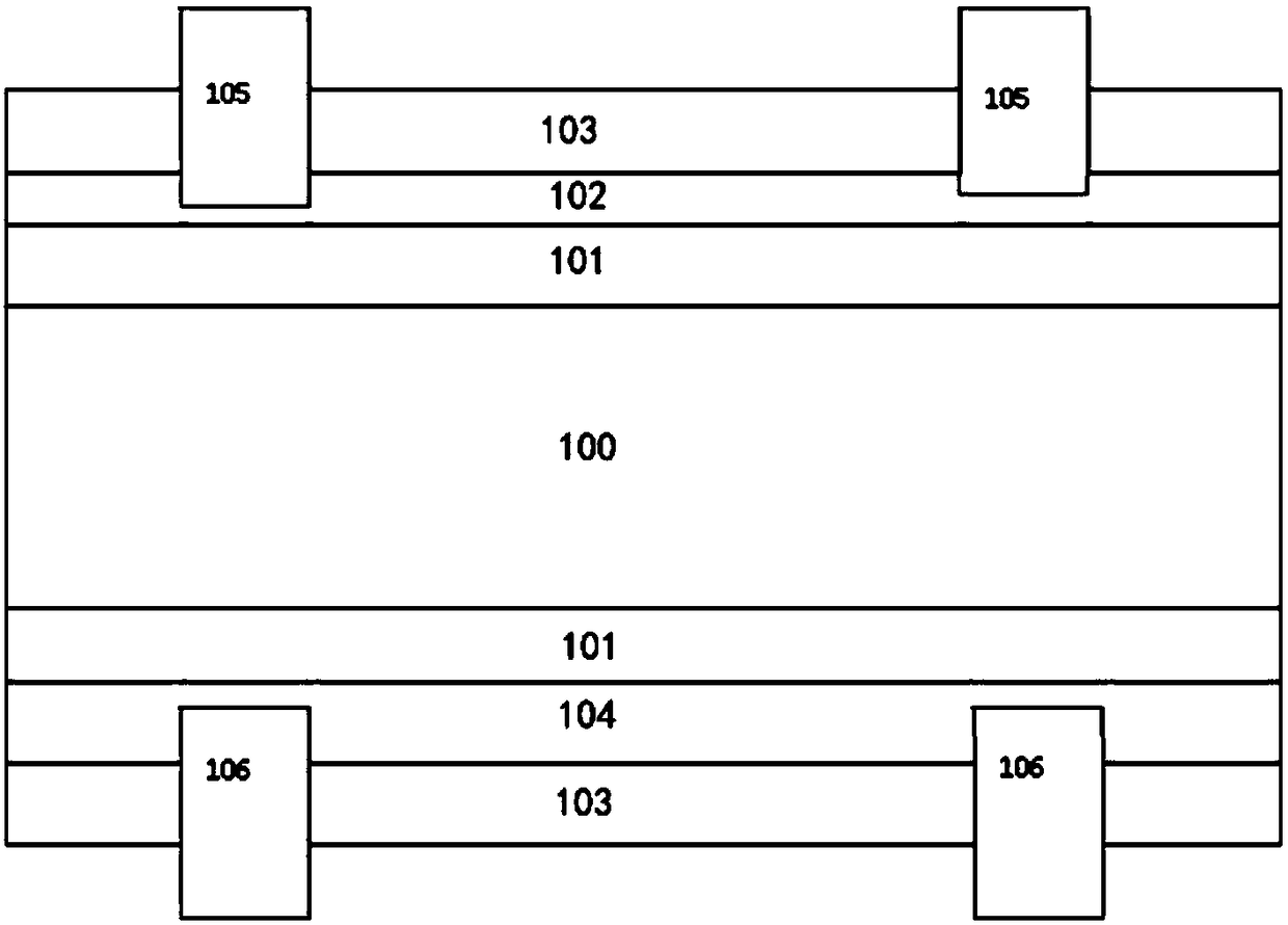
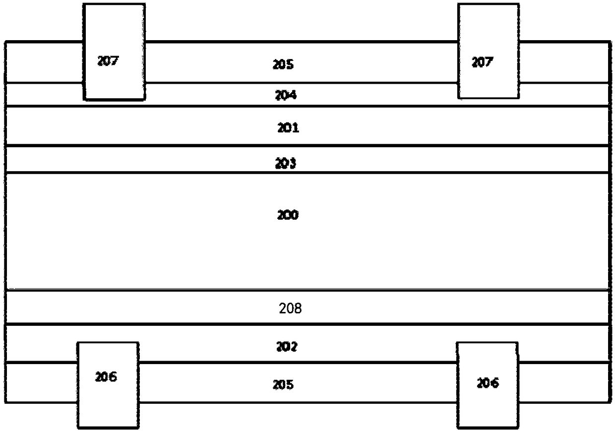
[0037] The preparation method of the N-type heterojunction bifacial solar cell proposed by the present invention will be further described in detail below with reference to the accompanying drawings and specific examples. Advantages and features of the present invention will be apparent from the following description and claims. It should be noted that all the drawings are in a very simplified form and use imprecise scales, and are only used to facilitate and clearly assist the purpose of illustrating the embodiments of the present invention.

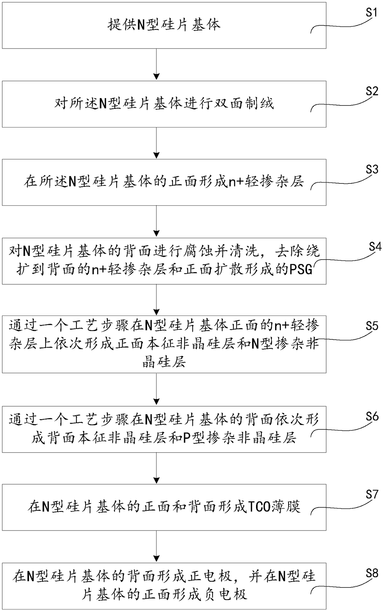
[0038] Please refer to Figure 2-Figure 3 ,Such as Figure 2-Figure 3 As shown, the embodiment of the present invention provides a method for preparing an N-type heterojunction double-sided solar cell, comprising the following steps:

[0039] S1: providing an N-type silicon wafer substrate 200;

[0040] S2: Perform double-sided texturing on the N-type silicon wafer substrate 200; specifically: put the N-type silicon wafer substrate 2...


PUM


Abstract

The invention discloses a preparation method of an N type heterojunction two-sided solar battery. The preparation method comprises the following steps of S1, providing an N type silicon wafer substrate; S2, performing two-sided texturing on the N type silicon wafer substrate; S3, forming an n+ lightly doped layer on the front surface of the N type silicon wafer substrate; S4, performing corrosionand cleaning on the back surface of the N type silicon wafer substrate; S5, forming a front surface intrinsic amorphous silicon layer and an N type doped amorphous silicon layer on the n+ lightly doped layer on the front surface of the N type silicon wafer substrate through a process step in sequence; S6, forming a back surface intrinsic amorphous silicon layer and a P type doped amorphous siliconlayer on the back surface of the N type silicon wafer substrate through a process step in sequence; S7, forming TCO thin films on the front surface and the back surface of the N type silicon wafer substrate; and S8, forming a positive electrode on the back surface of the N type silicon wafer substrate, and forming a negative electrode on the front surface thereof. By adoption of the method, a high surface passivation effect can be obtained, the problem that utilization of a window layer of a solar battery front surface is suppressed in the prior art can be solved, and the conversion efficiency of the battery can be improved.

Description

technical field [0001] The invention relates to the technical field of solar cells, in particular to a preparation method of an N-type heterojunction double-sided solar cell. Background technique [0002] Because of its cleanness, safety, convenience, and high efficiency, solar photovoltaic power generation has become an emerging industry that is widely concerned and focused on development by countries all over the world. Therefore, in-depth research and utilization of solar energy resources is of great significance to alleviate the resource crisis and improve the ecological environment. [0003] Among all kinds of solar cells, N-type heterojunction cell technology has relatively simple process steps, no light-induced attenuation, no potential-induced attenuation, low temperature coefficient, ultra-high cell conversion efficiency and double-sided power generation performance. At the forefront of research and industrialization. [0004] Taking conventional N-type heterojunc...

Claims


Application Information

Patent Timeline
Patent Type & Authority Applications(China)
IPC IPC(8): H01L31/0747H01L31/20
CPCH01L31/0747H01L31/202Y02E10/50
Inventor 屈小勇董鹏程基宽倪玉凤
Owner 青海黄河上游水电开发有限责任公司西宁太阳能电力分公司
Why Eureka
Try Eureka