A metal/air battery system

An air battery and air battery stack technology, applied in fuel cells, fuel cell additives, circuits, etc., can solve the problems of insufficient heat dissipation, the volume occupied by the main circuit, and the branch circuit cannot be too thin, so as to improve the anode utilization rate, The effect of improving flow consistency and increasing discharge capacity

Active Publication Date: 2021-02-09
DALIAN INST OF CHEM PHYSICS CHINESE ACAD OF SCI
View PDF5 Cites 0 Cited by
  • Summary
  • Abstract
  • Description
  • Claims
  • Application Information

AI Technical Summary

Problems solved by technology

However, there is a certain range for reducing the flow rate. If the flow rate is too low, the heat dissipation cannot meet the requirements; and there are certain limitations in increasing the diameter ratio of the main pipeline and the branch pipeline. The branch path should not be too thin; on the other hand, the larger the main path, the more volume it will occupy

Method used


Image

  • A metal/air battery system
  • A metal/air battery system
  • A metal/air battery system

Examples


Embodiment 1

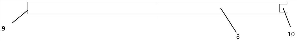
[0039] The structure of the battery pack is the same as in Example 1, but only one main liquid injection port and one main liquid discharge port are used in this embodiment, and a flow equalization unit is built in the main liquid injection channel, and the flow equalization unit is a separator structure , set along the direction of fluid flow, the width of the separator is 30 mm in diameter of the main liquid injection pipe, and the length is 600 mm, which is the same as the length of the main channel, and one end (9) of the separator is glued to the end of the main liquid injection port A (4) , divide the electrolyte injected into the middle of the main channel evenly into two parts, one part starts from the main liquid injection port A and directly injects into each single cell of the battery pack along the single cell liquid injection port, and the other part is divided by the injection part far away from the single cell side. The liquid flow channel brings the electrolyte ...

Embodiment 2

[0043] The structure of the battery pack is the same as that in Example 1, but in this example, a wedge-shaped partition is added in the main liquid injection channel. The cross-sectional shape of the partition is a right-angled triangle, and the length of the long side of the right-angled side is 600mm for the main liquid injection channel. , the length of the short side of the right-angled side is 4 / 5, and the diameter of the main liquid injection channel is 24mm. , is 15mm thick. When the electrolyte is injected into the side of the main liquid injection port A and flows through the triangular separator, the cross-sectional area of ​​the main channel gradually decreases, so that the static pressure at the entrance of each single cell is equal, and the electrolyte can be injected into the single cell more uniformly. The main liquid injection port B The A side is sealed by the end plate, and only the A side can be filled with liquid. Liquid injection was performed at 9L / min,...

Embodiment 3

[0047] The structure of the battery pack is the same as in Example 1, but in this example, a progressively increasing array of raised partitions is added to the main liquid injection channel. The length of the partition is 600mm for the main liquid injection channel, and the width is 4 / 5 The diameter of the flow channel is 24mm, and the distance between the stepped protrusions is 20mm from the liquid injection port of the single battery. Starting from the side A of the main liquid injection port, the left side of each stepped protrusion is located on the right side of the liquid injection port of the single battery. The height of the long side is 2 / 3 of the diameter of the main liquid injection channel, 20mm, and the stepped slope is that the side of the hypotenuse corresponds to the side of the single battery liquid injection port on the main channel. When the electrolyte is injected into the A side of the main liquid injection port and flows through the stepped separator, the...


PUM


Abstract

The invention provides a metal / air battery system, comprising a metal / air battery pack, a liquid pump, a heat exchanger and a liquid storage unit; the liquid inlet of the liquid pump is connected with the liquid storage unit, and the liquid outlet of the liquid pump The liquid outlet of the heat exchanger is connected with the liquid inlet of the heat exchanger, and the liquid discharge port of the heat exchanger is connected with the electrolyte injection port of the metal / air battery pack; the electrolyte liquid outlet of the metal / air battery pack is connected with the liquid storage unit to form a Closed circuit; the single cell includes a single cell casing, the metal anode in the surface of the single cell casing is perpendicular to the bottom of the single cell casing, and the air cathodes placed on opposite sides of the battery casing and parallel to the metal anode are formed by the single cell An electrolyte chamber composed of a battery case, a metal anode and an air cathode; from left to right, N cell cases are arranged parallel to each other and in sequence, and there are liquid injection main channels between the adjacent cell cases, The liquid discharge main flow channel and the air flow channel; the flow equalization unit is arranged in the liquid injection main flow channel.

Description

technical field [0001] The invention relates to a metal / air battery system, in particular to a metal / air battery system with high consistency. Background technique [0002] A metal / air battery is an electrochemical reaction device that uses metal (such as magnesium, aluminum, zinc, etc.) as the anode fuel, oxygen in the air as the oxidant, and lye as the electrolyte solution. my country's magnesium, aluminum, zinc and other metals are rich in reserves and low in price, so metal / air batteries have broad application prospects in many fields of mobile power sources such as communication power supplies, field emergency power supplies, lighting power supplies, and reserve power supplies. [0003] Since the working voltage of metal / air battery cells is only 1-1.5V, when encountering electrical equipment with higher rated voltage requirements, it is often necessary to connect multiple metal / air cells in series to obtain higher voltage. At the same time, due to the chemical reactio...

Claims


Application Information

Patent Timeline
Patent Type & Authority Patents(China)
IPC IPC(8): H01M12/06H01M8/04276H01M8/04701H01M8/04029
CPCH01M8/04029H01M8/04283H01M8/04708H01M12/06Y02E60/50
Inventor 孙公权刘敏王二东
Owner DALIAN INST OF CHEM PHYSICS CHINESE ACAD OF SCI
Why Eureka
Try Eureka