Electromagnetic valve for hydraulic media

A hydraulic medium and solenoid valve technology, applied in the field of solenoid valves, can solve problems such as wear and tear, and achieve the effects of improved sliding characteristics and life, and low eddy current loss

Inactive Publication Date: 2002-03-27
WAERTSILAE SCHWEIZ AG
View PDF2 Cites 2 Cited by
  • Summary
  • Abstract
  • Description
  • Claims
  • Application Information

AI Technical Summary

Problems solved by technology

With this valve, the switching time will undoubtedly be very short, but the wear, especially at the control edge, will be very significant, so the slide valve must be replaced after a relatively small number of switching actions.

Method used


Image

  • Electromagnetic valve for hydraulic media
  • Electromagnetic valve for hydraulic media
  • Electromagnetic valve for hydraulic media

Examples


Embodiment Construction

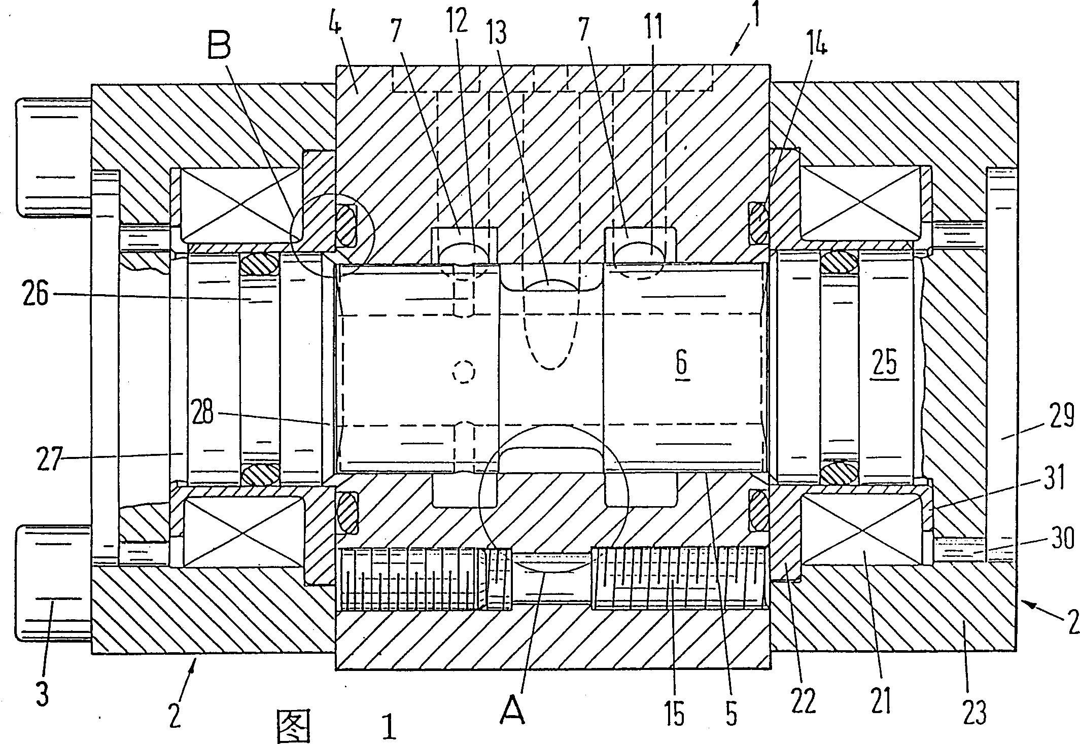
[0012] The valve essentially comprises a valve part 1 and two drive parts 2 which are formed as electromagnets and mounted on the valve part 1 by means of screws 3 .

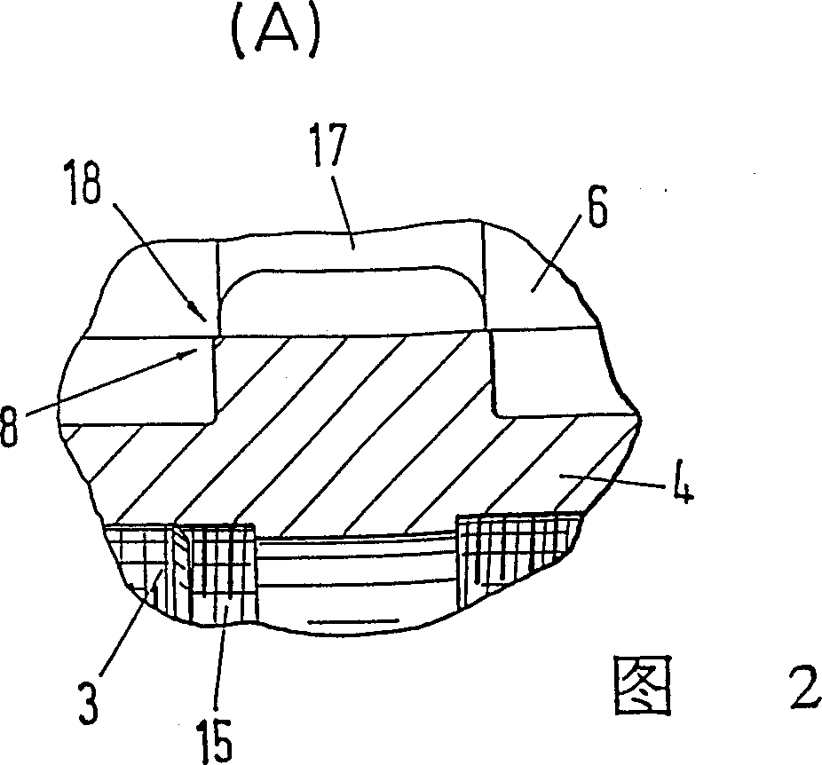
[0013] The valve part 1 comprises a housing 4 with a through opening 5 along the cylinder axis and a slide valve or valve plug 6 arranged to be movable back and forth in the through opening. The housing 4 is composed of magnetic material. It can be seen from FIG. 1 that the length of the valve housing 4 is less than 2.5 times the outer diameter of the slide valve 6 . Two annular grooves 7 are formed in the housing 4 and are formed to run parallel in the through-hole 5 in such a way that each of the adjacently located edges forms a control edge 8 ( FIG. 2 ). In addition, a supply passage 11 and a return passage 12 each leading to the ring groove 7 and a user passage 13 leading to the through hole 5 are formed in the housing. An annular cutout is provided on the end face of the housing for receiving the sealing ...


PUM


Abstract

The electromagnetic valve has a valve housing (4) enclosing a valve slider (6) contained within a housing bore (13) and a pair of electromagnets (2) for controlling the valve movement between 2 alternate end positions, the remanent magnetism holding the valve slider in the obtained end position. The valve bore within the valve housing and the valve slider are each provided with a hard surface coating of titanium nitrite, wolfram carbide, or similar. The length of the valve housing may be less than 2.5 times the outer diameter of the valve slider.

Description

technical field [0001] The present invention relates to a solenoid valve for hydraulic media, which comprises a valve housing, a spool valve and two electromagnets, the spool valve can be moved whenever the electromagnet is energized and the spool valve can be moved by the remaining when the energizing voltage is cut off. Magnetic holds firmly. Background technique [0002] Such valves are known and comprise a housing and a valve plug or slide valve which is displaceably arranged in the housing. An armature part, to which the electromagnet is in each case connected, is arranged on each end face of the slide valve in such a way that the valve body can in each case be displaced when the electromagnet is activated. With such a valve switching times will undoubtedly be short, but wear, especially at the control edges, will be very noticeable, so that the slide valve must be replaced after a relatively small number of switching movements. Contents of the invention [0003] It...

Claims


Application Information

Patent Timeline
IPC IPC(8): F15B13/044F16K31/06
CPCF15B13/044F16K31/0679F16K31/0613Y10T137/8671Y10T137/86622
Inventor A·F·万德尔
Owner WAERTSILAE SCHWEIZ AG
Why Eureka
Try Eureka