
Modular area cooling system

A cooling system and modular technology, applied in the field of modular district cooling system, can solve the problems of urban construction and environmental impact, need to be placed on the roof of other buildings, increase the energy consumption of cooling water pump transportation, etc., so as to reduce the transmission of pipe network. Energy consumption and cooling loss, optimizing equipment layout and pipelines, and improving the effect of main engine operating conditions

Active Publication Date: 2018-06-19
ARCHITECTURAL DESIGN & RES INST OF SOUTH CHINA UNIV OF TECH
View PDF7 Cites 2 Cited by
  • Summary
  • Abstract
  • Description
  • Claims
  • Application Information

AI Technical Summary

Problems solved by technology

[0003] 1. Refrigeration energy consumption problem; in order to realize cooling with a large temperature difference, the refrigeration host needs to operate at a low temperature condition. The decrease in chilled water outlet temperature causes a rapid decline in the efficiency of the host. Under the same cooling capacity, the energy consumption increases, and the efficient operation of the host cannot be fully utilized.
[0004] 2. The problem of chilled water transportation; the small temperature difference and large flow characteristics of the district cooling system lead to high energy consumption of chilled water transportation, accounting for about 8.5% of the energy consumption of the entire system, which is much higher than the cooling loss
At the same time, it also restricts the radius of district cooling
In addition, the commonly used chilled water secondary pump and the delivery system composed of branched pipe network, in order to meet the most unfavorable users, the selection of the lift of the secondary pump is too large, often there are near-end users who need to throttle, and the far-end users need to use the pressure head. Insufficient situation, so the user end needs to strictly control the resistance loss, resulting in double waste of energy waste and investment
[0005] 3. Cooling problem; cooling stations are often built in the load center, which is limited by land use, installed capacity, construction form, environmental noise, etc., and the installed capacity is often limited due to the limited area of ​​ground cooling towers, which cannot make full use of regional cooling Intensification, scale effect
When the cooling tower is running, it is easy to form noise pollution
When the cooling station adopts the underground or semi-underground form such as attached type, the cooling tower needs to be placed on the roof of other buildings, which will have a great impact on urban construction and the environment, and at the same time increase the energy consumption of the cooling water pump; even if a stand-alone building is used, the cooling tower When placed centrally on the roof of the cooling station, the local heat island caused by the cluster effect will reduce the operating efficiency of the cooling tower and affect the energy consumption of the host

Method used


Image

  • Modular area cooling system
  • Modular area cooling system

Examples


Embodiment Construction

[0027] The present invention will be further described in detail below in conjunction with the embodiments and the accompanying drawings, but the embodiments of the present invention are not limited thereto.

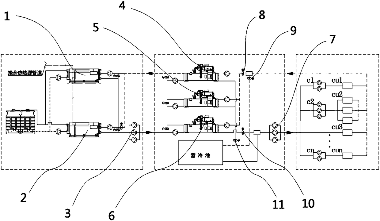
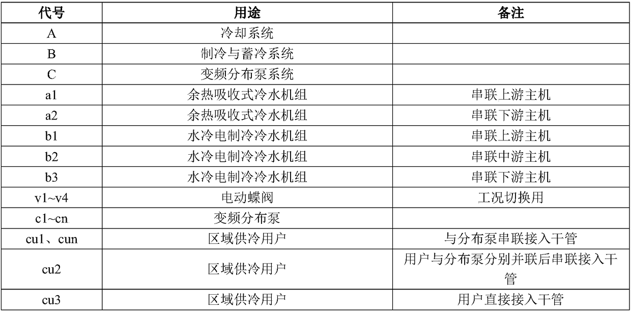
[0028] Such as figure 1 , a modular district cooling system, including a cooling system A, a refrigeration and cold storage system B, and a variable frequency distribution pump system C, wherein

[0029] The cooling system includes waste heat source pipeline, waste heat absorption chiller a1, cooling system waste heat absorption chiller a2, cooling water delivery pump BQ; among them, the waste heat heat source pipeline transports waste heat to drive the waste heat absorption chiller a1 running in series, and the cooling system waste heat absorption Type chiller a2, cooling the cooling return water to obtain low-temperature cooling water, and the low-temperature cooling water is transported to the refrigeration and cold storage system through the cooling water delivery pu...


PUM


Abstract

The invention discloses a modular area cooling system. The cooling system comprises a cooling system, a refrigerating and cold storage system and a variable frequency distribution pump system, whereinthe cooling system comprises a waste heat source pipeline, a waste heat absorption type water chilling unit a1, a cooling system waste heat absorption type water chilling unit a2 and a cooling waterconveying water pump BQ; the refrigerating and cold storage system comprises a water-cooled electric cooling water chilling unit b1, a water-cooled electric cooling water chilling unit b2, a water-cooled electric cooling water chilling unit b3, an electric butterfly valve v1, an electric butterfly valve v2, an electric butterfly valve v3, an electric butterfly valve v4, a cold storage tank, a water distributor and a chilled water secondary pump BL; the cooling water conveying water pump BQ is used for conveying cooling water to a cold supply station, and the water-cooled electric cooling waterchilling units b1, the water-cooled electric cooling water chilling unit b2 and the water-cooled electric cooling water chilling unit b3 are used for extracting cooling water according to requirements by utilizing split cooling water pumps and utilizing the cooling water step by step; and the water-cooled electric cooling water chilling unit b1, the water-cooled electric cooling water chilling unit b2 and the water-cooled electric cooling water chilling unit b3 are connected with the cold accumulation pool in series and in parallel in a switched operation working condition through the electric butterfly valve v1, the electric butterfly valve v2, the electric butterfly valve v3 and the electric butterfly valve v4. According to the system, the installed capacity and the running efficiency of the cold supply station can be improved, and the advantages of intensive cooling, intensive energy utilization and efficient utilization of energy can be brought into full play.

Description

technical field [0001] The invention relates to the field of district cooling, in particular to a modularized district cooling system. Background technique [0002] In recent years, district central cooling, as a highly intensive and efficient energy utilization technology, has been vigorously promoted in China and has made outstanding contributions to urban energy supply, low-carbon construction, energy conservation and emission reduction, and green development. With the actual advancement of the project, a series of problems faced by district cooling have become more and more prominent, even restricting its actual promotion and application. Judging from the district cooling projects that have recently flourished in the south of my country and are advancing to the north, there are three main problems: [0003] 1. Refrigeration energy consumption problem; in order to realize cooling with a large temperature difference, the refrigeration host needs to operate at a low temper...

Claims


Application Information

Patent Timeline
Patent Type & Authority Applications(China)
IPC IPC(8): F25B30/06
CPCF25B30/06Y02B30/70
Inventor 王明超王钊邹玉进彭蓉
Owner ARCHITECTURAL DESIGN & RES INST OF SOUTH CHINA UNIV OF TECH
Learn More