
Multi-joint heavy load mechanical arm driven by single-blade hydraulic swing oil cylinders

A hydraulic swing, single-blade technology, used in manipulators, program-controlled manipulators, joints, etc., can solve the problems of delayed work process, long development cycle, self-weight ratio, low power density, etc.

Inactive Publication Date: 2018-06-22
WUHAN UNIV OF SCI & TECH
View PDF6 Cites 8 Cited by
  • Summary
  • Abstract
  • Description
  • Claims
  • Application Information

AI Technical Summary

Problems solved by technology

However, traditional industrial robots have a long development cycle and are designed based on specific tasks. After the structural size is designed, it cannot be changed and adjusted, and its ability to change according to requirements is very weak.
The design of the robot usually designs the body structure of each section of the robot arm according to the actual working situation and environmental conditions, which not only makes the robot work in a single form, but also makes it difficult for the designed robot components to be used in common with other robots. If it is damaged, the manipulator will not be repaired within a certain period of time and its working process will be delayed; that is, most of the existing manipulators are of non-modular design, and the versatility of the components is very poor; therefore, the modular design of the robot-driven joints is also an inevitable trend of development
The driving joints of existing industrial robots mainly adopt the form of servo motor plus harmonic reducer, which is bulky and the driving torque generated by the servo motor is very small, that is, the load-weight ratio and power density of the mechanical arm driven by the motor Very small, not suitable for handling large materials

Method used


Image

  • Multi-joint heavy load mechanical arm driven by single-blade hydraulic swing oil cylinders
  • Multi-joint heavy load mechanical arm driven by single-blade hydraulic swing oil cylinders
  • Multi-joint heavy load mechanical arm driven by single-blade hydraulic swing oil cylinders

Examples


Embodiment Construction

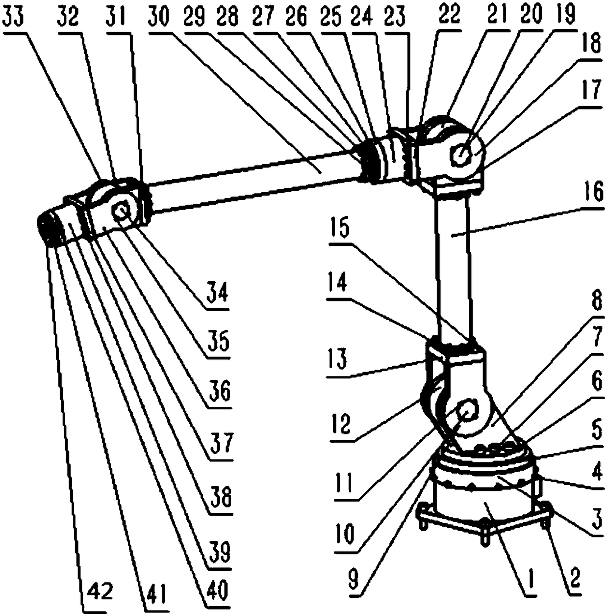
[0024] Below by embodiment, in conjunction with accompanying drawing, the technical scheme of the present invention is described further specifically, as figure 1 As shown, the multi-joint heavy-duty mechanical arm of the present invention is mainly composed of a base module, a waist joint module, a shoulder joint module, a wrist joint module, a large arm, a small arm, flanges, and bolts composed of six single-blade hydraulic swing cylinders. The J1 cylinder and J2 cylinder, the J3 cylinder and the J4 cylinder, the J5 cylinder and the J6 cylinder are all vertically arranged to form the waist joint module, the shoulder joint module and the wrist joint module respectively. The installation of the J1 cylinder and related parts In the base, the positioning bolts of the base can be connected with the ground or the workbench according to the work requirements.

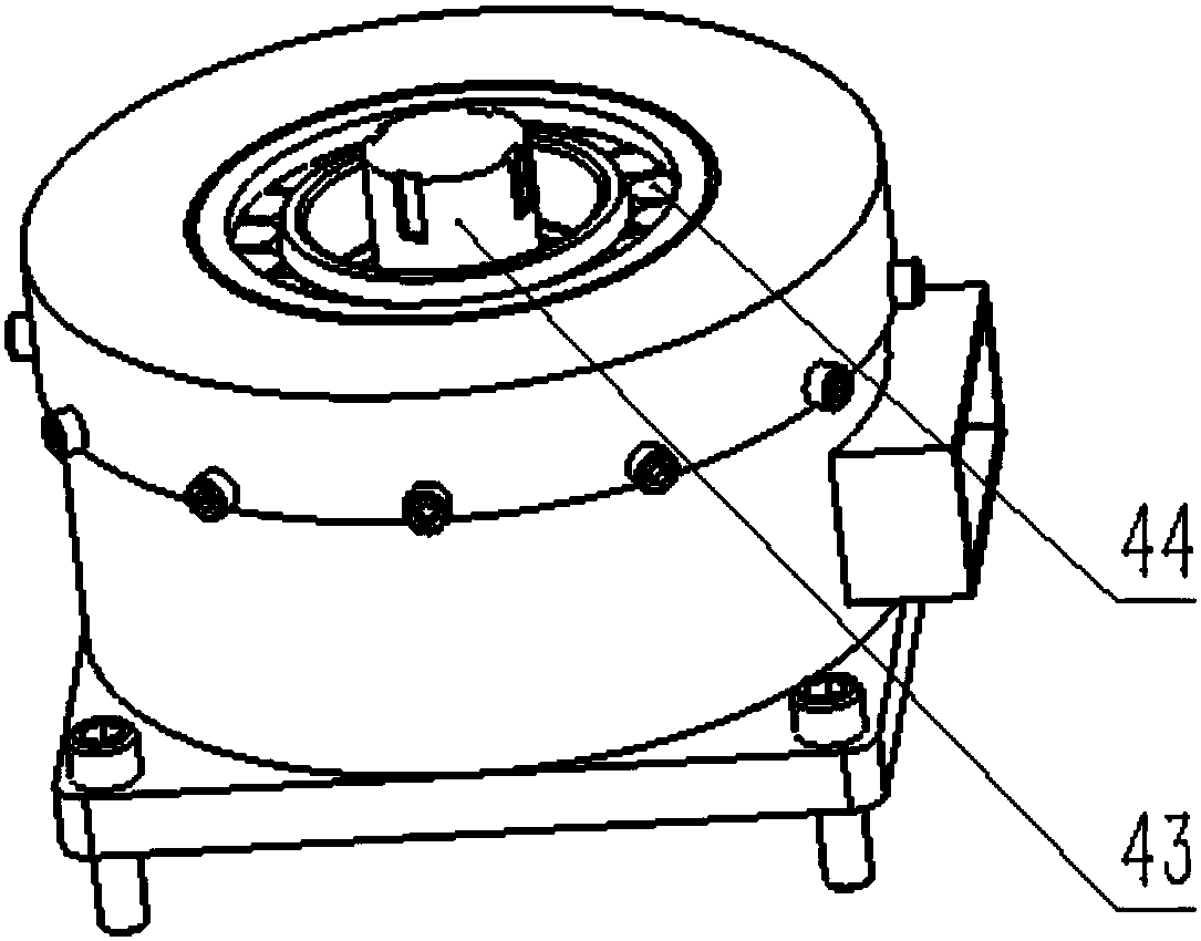
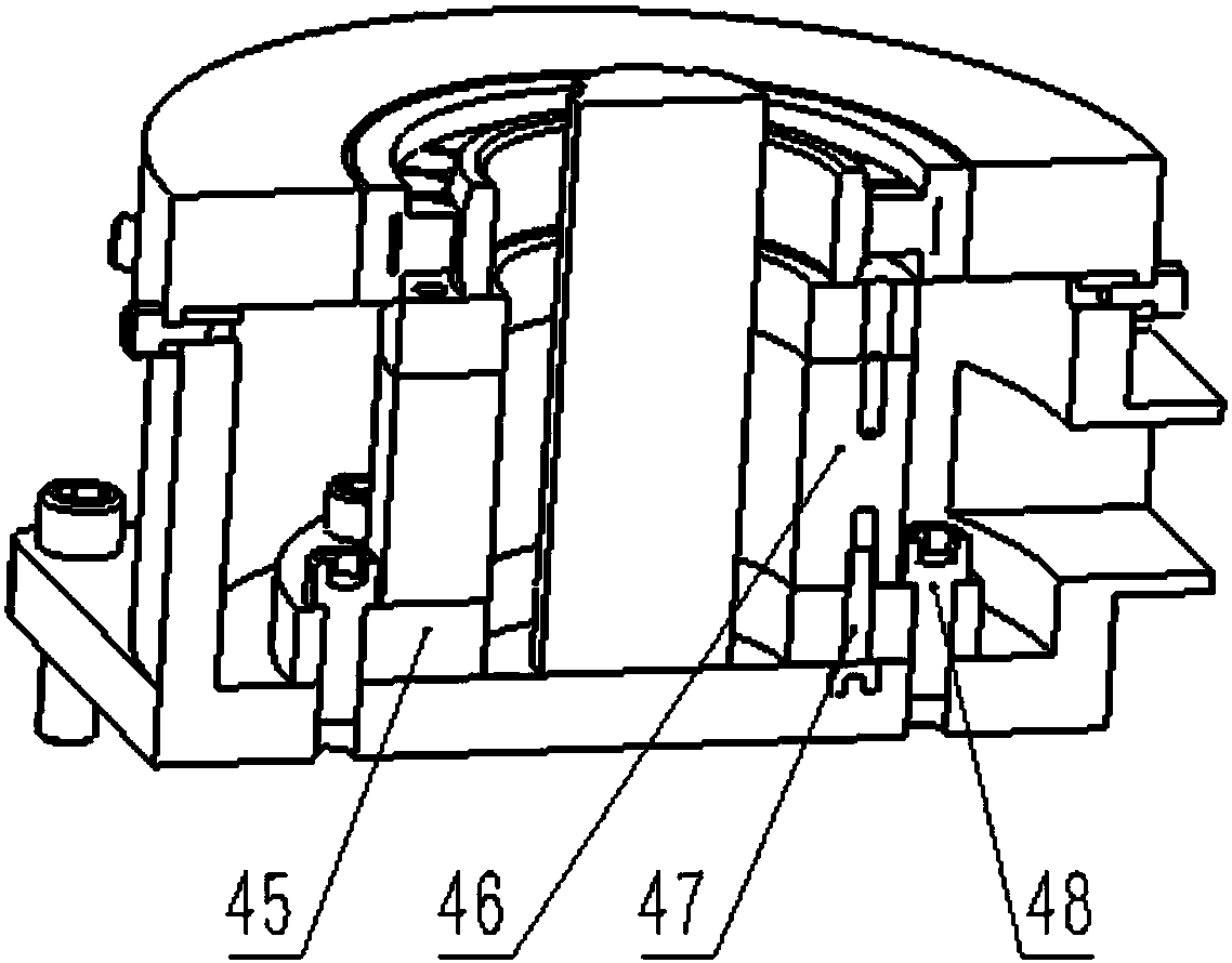
[0025] figure 2 and image 3 Shown are the base module and the sectional view of the base module respectively, the J1 o...


PUM


Abstract

The invention provides a multi-joint heavy load mechanical arm driven by single-blade hydraulic swing oil cylinders. The mechanical arm comprises a base module, a waist joint module, a shoulder jointmodule, a wrist joint module, a large arm and a small arm, wherein the large arm and the small arm are arranged between the modules. The mechanical arm is characterized in that the waist joint module,the shoulder joint module and the wrist joint module are each composed of two perpendicularly-arranged single-blade hydraulic swing oil cylinders. Every two adjacent modules are connected in series and fixed through a flange plate and a bolt, and large torque is transferred in a hydraulic drive mode. The waist joint module and the base module are in matched connection, the waist joint module comprises a J1 oil cylinder and a J2 oil cylinder which are perpendicularly arranged, the shoulder joint module comprises a J3 oil cylinder and a J4 oil cylinder which are perpendicularly arranged, and the wrist joint module comprises a J5 oil cylinder and a J6 oil cylinder which are perpendicularly arranged. The modules in the mechanical arm can be produced in batch, the production cost is reduced, the production efficiency is improved, the overall structure is simple and compact, and disassembly, assembly, overhaul and maintenance are convenient.

Description

technical field [0001] The invention belongs to the technical field of hydraulic robots, and in particular relates to a multi-joint heavy-duty mechanical arm driven by a single-blade hydraulic swing oil cylinder. Background technique [0002] The robotic arm is currently the most widely used automated mechanical device in the field of robotics. The widespread use of robotic arms in industrial production processes not only greatly reduces labor costs, but also greatly improves production efficiency and promotes industrial production. However, traditional industrial robots have a long development cycle and are designed according to specific tasks. After the structural dimensions are designed, they cannot be changed and adjusted, and their ability to change according to requirements is very weak. The design of the robot usually designs the body structure of each section of the robot arm according to the actual working situation and environmental conditions, which not only makes...

Claims


Application Information

Patent Timeline
IPC IPC(8): B25J9/14B25J17/00
CPCB25J9/148B25J17/00
Inventor 罗刚谢良喜加闯李昭罗中正
Owner WUHAN UNIV OF SCI & TECH
Learn More