Plug-in type single-motor hybrid electric vehicle transmission

A hybrid vehicle and transmission technology, which is applied in the arrangement of multiple different prime movers of power units, pneumatic power units, and general power units, etc., can solve the problem of difficulty in guaranteeing motors, limited speed regulation range, and loss of mechanical energy to electrical energy. And other issues

Active Publication Date: 2018-06-26
吉林省晟林汽车传动科技有限公司
View PDF7 Cites 13 Cited by
  • Summary
  • Abstract
  • Description
  • Claims
  • Application Information

AI Technical Summary

Problems solved by technology

[0003] Although there are many inventions of hybrid transmission technology at home and abroad, and these inventions have achieved obvious technological progress and economic effects, their structure should have shortcomings. The power loss of the first motor doing useless work; another example is that in Honda's i-MMD system, the engine is only suitable for direct drive when cruising at high speed, and the other working conditions are to drive the generator to generate electricity, so there is a loss of mechanical energy converted to electrical energy, and the battery is charged. loss, loss of battery discharge, loss of electrical energy to mechanical energy
Moreover, Toyota's ECVT and Honda's i-MMD both use a fixed transmission ratio, and only use the large speed regulation range of the motor for stepless transmission. The speed regulation range is limited, and it is difficult to ensure that the motor works in the highest efficiency range. Both power and economy are affected

Method used


Image

  • Plug-in type single-motor hybrid electric vehicle transmission
  • Plug-in type single-motor hybrid electric vehicle transmission
  • Plug-in type single-motor hybrid electric vehicle transmission

Examples


Embodiment Construction

[0017] The present invention will be further described below in conjunction with the accompanying drawings and specific embodiments.

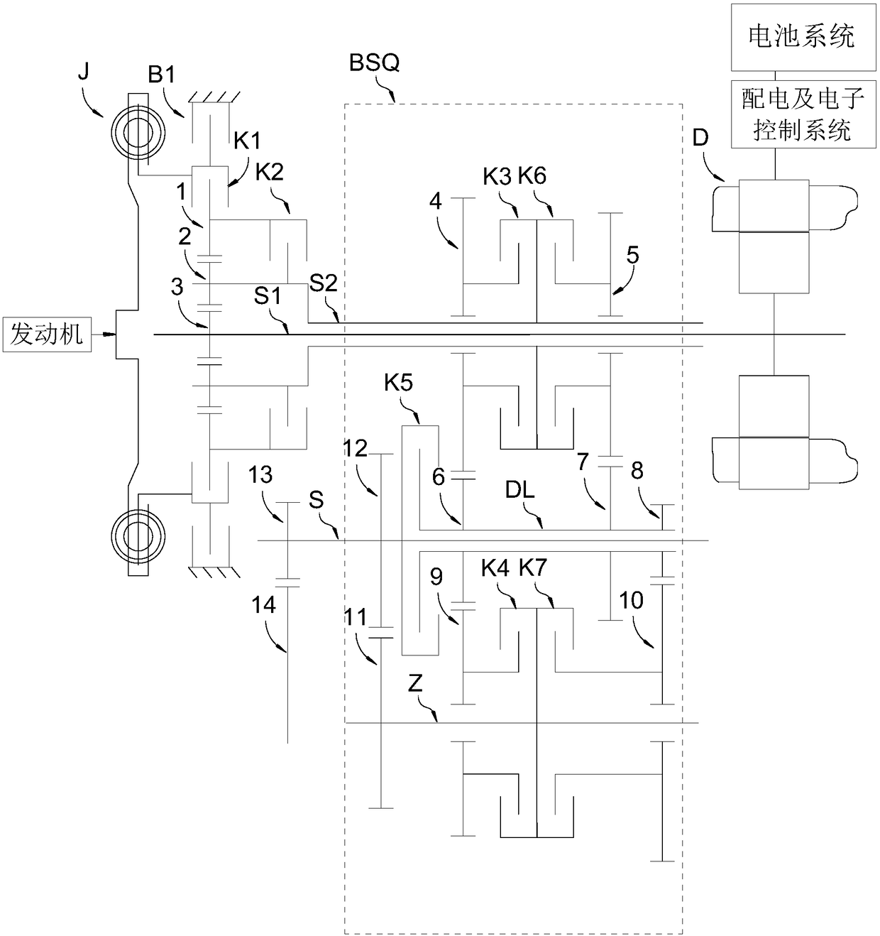
[0018] figure 1It is a schematic structural diagram of the first embodiment of the plug-in single-motor hybrid electric vehicle transmission of the present invention, the solution of the first embodiment is the preferred solution of the present invention, and the first implementation of the plug-in single-motor hybrid electric vehicle transmission of the present invention The mechanical transmission system BSQ in the example adopts the structural scheme of the 6-speed MAT automatic transmission inside, as shown in the figure, the plug-in single-motor hybrid vehicle transmission of the present invention includes a flywheel shock absorber J arranged between the transmission and the engine, The engine connection clutch K1 that controls the connection between the engine and the transmission, the planetary gear set that adjusts the power flow of the...


PUM


Abstract

The invention discloses a plug-in type single-motor hybrid electric vehicle transmission which comprises a flywheel shock absorber, an engine connecting clutch, a planet gear set, a gear ring, a planet carrier, a sun gear and a planet row control clutch, wherein the gear ring, the planet carrier, the sun gear and the planet row control clutch are arranged in the planet gear set. The transmission further comprises a motor integrating a starting function, a drive function and a power generating function, a motor shaft connecting the motor with the sun gear, a brake controlling the gear ring to be fixed or rotate, a mechanical speed change system taking charge of transmission gear changes, an input shaft connecting the planet carrier with the mechanical speed change system, an output shaft connecting the mechanical speed change system with a main speed reducer, a battery system and a power distribution and electronic control system. The transmission has the beneficial effects that the structure of a single-motor system, a power synthetic system and the mechanical speed change system is adopted, the power performance is excellent, an engine and the motor work in the most economical rotation speed section, stepless speed regulation is matched with mechanical stepping gear shifting in the acceleration process, acceleration power is not interrupted, and the gear shifting efficiency and the gear shifting smoothness are extremely high.

Description

technical field [0001] The invention belongs to the field of automobile transmissions, in particular to hybrid transmissions for new energy vehicles. Background technique [0002] The transmission is the most important transmission component in the power transmission system of the car. The performance of the transmission directly determines the performance of the car, determines the transmission efficiency of the car, determines the fuel economy of the car, and determines the smoothness and comfort of the car's gear shifting. In the transmission structure with polar transmission, the multi-wheel axle structure of Chinese patent ZL201520304746.1 is the structure with the least number of gears in the same gear. Under the same gear machining accuracy, the gear transmission efficiency of its 9-speed structure is 9 times higher than that of ZF. The gear transmission efficiency of the transmission is still high. Due to the unique structural arrangement, the position of the gears a...

Claims


Application Information

Patent Timeline
Patent Type & Authority Applications(China)
IPC IPC(8): B60K6/547F16H61/04
CPCF16H61/04B60K6/547F16H2061/0015Y02T10/62
Inventor 雷胜林雷世庆陈爽王显达李盛其雷嘉懿
Owner 吉林省晟林汽车传动科技有限公司
Why Eureka
Try Eureka