
Permanent magnet synchronous motor rotor position estimation method based on rotating high-frequency injection algorithm

A permanent magnet synchronous motor, rotor position technology, applied in the control of generator, motor control, motor generator control and other directions, can solve the problem of low accuracy of estimated rotor position, low signal-to-noise ratio, phase lag and so on

Active Publication Date: 2018-06-26
LISHUI BOYUAN TECH CO LTD
View PDF4 Cites 15 Cited by
  • Summary
  • Abstract
  • Description
  • Claims
  • Application Information

AI Technical Summary

Problems solved by technology

However, the signal-to-noise ratio of this high-frequency rotation injection method is low in the process of estimating the rotor position signal, and there is a phase lag phenomenon, which leads to low precision in estimating the rotor position.

Method used


Image

  • Permanent magnet synchronous motor rotor position estimation method based on rotating high-frequency injection algorithm
  • Permanent magnet synchronous motor rotor position estimation method based on rotating high-frequency injection algorithm
  • Permanent magnet synchronous motor rotor position estimation method based on rotating high-frequency injection algorithm

Examples


Embodiment Construction

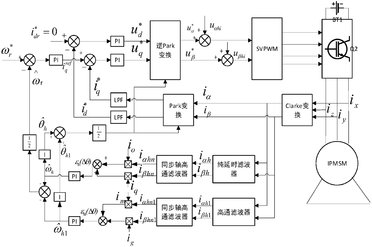
[0048] The present invention will be further described below in conjunction with the accompanying drawings.

[0049] Refer to attached figure 1 , the realization of the present invention is as follows:

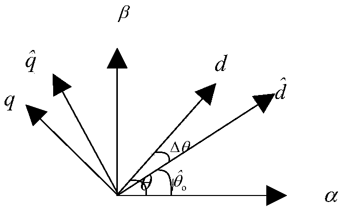
[0050] Step 1, define the coordinate system relationship graph.

[0051] refer to figure 2 , the coordinate system defined in this step includes three coordinate systems: the two-phase stationary coordinate system, the estimated two-phase synchronous rotating coordinate system, and the real two-phase synchronously rotating coordinate system, where: α-β is the two-phase stationary coordinate system, and d-q is The actual rotor synchronously rotating coordinate system, To estimate the rotor synchronous rotating coordinate system;

[0052] Define the rotor estimated position error as in is the estimated value of the rotor position, and θ is the actual value of the rotor position.

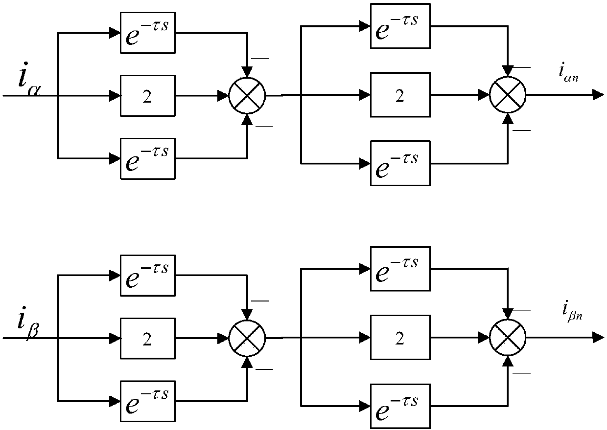
[0053] Step 2, inject different signals u in the two-phase stationary coordinate system ...


PUM


Abstract

The invention provides a permanent magnet synchronous motor rotor position estimation method based on rotating high-frequency injection algorithm, mainly solving the problem in the prior art that therotor position estimation accuracy is low caused by low signal to noise ratio of the rotor position signal. The permanent magnet synchronous motor rotor position estimation method based on the rotating high-frequency injection algorithm comprises the following steps: firstly, injecting two different rotating high-frequency voltage signals into the static coordinate system to obtain high-frequencycurrent responses, and using the pure time-delay filter to obtain the high-frequency current signal responses with angular frequency of [Omega]h separately; obtaining high-frequency current signal responses with the angular frequency of [Omega]h1 using a high-pass filter; and obtaining two estimation values according to the two obtained high-frequency signal responses, and calculating the averageto obtain the final rotor position estimation value (shown in the description). According to the permanent magnet synchronous motor rotor position estimation method based on the rotating high-frequency injection algorithm, two different rotating high-frequency voltage signals are injected into the static coordinate system, therefore, the estimation value is more reliable; meanwhile, the pure time-delay filter is used, therefore, the signal to noise ratio is improved, the phase lag phenomenon is reduced, and the position accuracy of the estimated rotor is finally improved. The permanent magnetsynchronous motor rotor position estimation method based on the rotating high-frequency injection algorithm can be used for the motor control system.

Description

technical field [0001] The invention belongs to the technical field of position sensorless control, in particular to a method for estimating the rotor position of a permanent magnet synchronous motor, which can be used in a motor control system. Background technique [0002] In order to realize the optimal voltage vector control or the maximum torque control, it is necessary to obtain the position information of the permanent magnet synchronous motor rotor accurately. At present, the methods for obtaining the rotor position of the permanent magnet synchronous motor mainly include the method of direct detection by using a position sensor and the method of estimation and detection without a position sensor. in: [0003] The method of direct detection by the position sensor is mainly to place a mechanical sensor in the permanent magnet synchronous motor, and directly detect the rotor position through the sensor. However, the reliability and control accuracy of this method is ...

Claims


Application Information

Patent Timeline
IPC IPC(8): H02P21/18
CPCH02P21/18H02P2203/03H02P2203/11
Inventor 薛飞汪顺长杨正森罗彬
Owner LISHUI BOYUAN TECH CO LTD
Learn More