Bidirectional force-bearing slurry bearing device and rotating guiding tool utilizing same
A bearing device and rotational guidance technology, applied in the direction of bearings, bearing components, shafts and bearings, etc., can solve the problems of reduced life of rolling bearings, inability to work with high life, and the inability of conventional rolling bearings to withstand bidirectional axial forces. Increased force, high drilling life and low bending stress
- Summary
- Abstract
- Description
- Claims
- Application Information
AI Technical Summary
Problems solved by technology
Method used
Image
Examples
Embodiment 2
[0069] This embodiment provides a static push-in articulated high-deflection-rate rotary steering tool with a generator drill collar nipple. Among them, the static internal push against the articulated high-inclination-rate rotary steering tool is the same as that of Embodiment 1, and the specific implementation is as follows:
[0070] Such as image 3 As shown, in this embodiment, the mud turbine generator 18 that provides electric energy is positioned on the inner shoulder of the drill collar 17 nipple, and the lower end interface 18.1 of the generator is plugged into the upper end interface 11.1 of the rotary steerable tool to realize the drill collar with a generator. Electrical connection of pup joints to rotary steerable tools. Due to the separate assembly of the generator pup joint and the drill collar of the rotary steerable tool, it has the characteristics of flexible and convenient assembly, easy processing and manufacturing of the rotary mandrel drill collar 7, and...
Embodiment 3
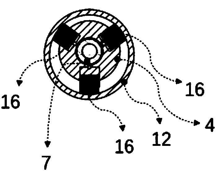
[0076] This embodiment provides a static pushing type high-inclination rate rotary steering tool. The difference from Embodiment 1 is that this embodiment also provides a second non-rotating outer casing 12 structure to increase the second non-rotating outer casing and The rotation frictional resistance of the well wall realizes that the second non-rotating jacket always maintains a quasi-stationary state. See Figures 5A-5F shown. The specific implementation is as follows:
[0077] The second non-rotating overcoat 12 has wear-resistant ribs 12.1, and the wear-resistant ribs are straight wings. The outer circle of the wear-resistant rib is a zigzag structure, and a number of hard alloy blocks are inlaid between the zigzag structures to increase the wear resistance of the wear-resistant rib 12.1. At the same time, the wear-resistant ribs 12.1 can be 3 groups, 4 groups, or 6 groups, which are evenly distributed on the outer circle of the second non-rotating jacket 12. The spe...
Embodiment 4
[0079] A two-way load-bearing mud bearing device, which can be applied to the static pushing type high-inclination-rate rotary guide tool described in Embodiments 1-3. Such as Figure 11-12 As shown, the two-way load-bearing mud bearing device is arranged between the non-rotating outer casing at the lower part of the rotary steerable tool and the drill bit shaft 15, and is used to isolate the rotational movement of the drill bit shaft 15 so that the non-rotating motion of the rotary steerable tool The casing does not rotate relative to the ground, wherein the "non-rotating casing" mentioned in the embodiments is the second non-rotating casing 12 mentioned in Embodiments 1-3.
[0080] The two-way force-bearing mud bearing device includes a set of radial bearing support surface structures and two sets of axial bearing support surface structures, so that the non-rotating outer sleeve of the rotating guide tool bears two-way axial force, and the two-way force-bearing A mud bearin...
PUM
 Abstract
Description
Claims
Application Information
 - R&D
- Intellectual Property
- Life Sciences
- Materials
- Tech Scout
- Unparalleled Data Quality
- Higher Quality Content
- 60% Fewer Hallucinations
Browse by: Latest US Patents, China's latest patents, Technical Efficacy Thesaurus, Application Domain, Technology Topic, Popular Technical Reports.
© 2025 PatSnap. All rights reserved.Legal|Privacy policy|Modern Slavery Act Transparency Statement|Sitemap|About US| Contact US: help@patsnap.com


