Integrated circuit analysis system and method with partially evacuated volume for electron beam manipulation

An integrated circuit, electron beam technology, applied in the field of integrated circuit analysis systems and methods with a local evacuation volume for electron beam operation, can solve problems such as slowness, cumbersomeness, etc.

Active Publication Date: 2022-01-11
FEI CO
View PDF10 Cites 0 Cited by
  • Summary
  • Abstract
  • Description
  • Claims
  • Application Information

AI Technical Summary

Problems solved by technology

Previous e-beam solutions all relied on "passing" electrical signals into the SEM's vacuum chamber, a cumbersome and slow process that may require the production of specialized connection devices for specific ICs

Method used


Image

  • Integrated circuit analysis system and method with partially evacuated volume for electron beam manipulation
  • Integrated circuit analysis system and method with partially evacuated volume for electron beam manipulation
  • Integrated circuit analysis system and method with partially evacuated volume for electron beam manipulation

Examples


Embodiment Construction

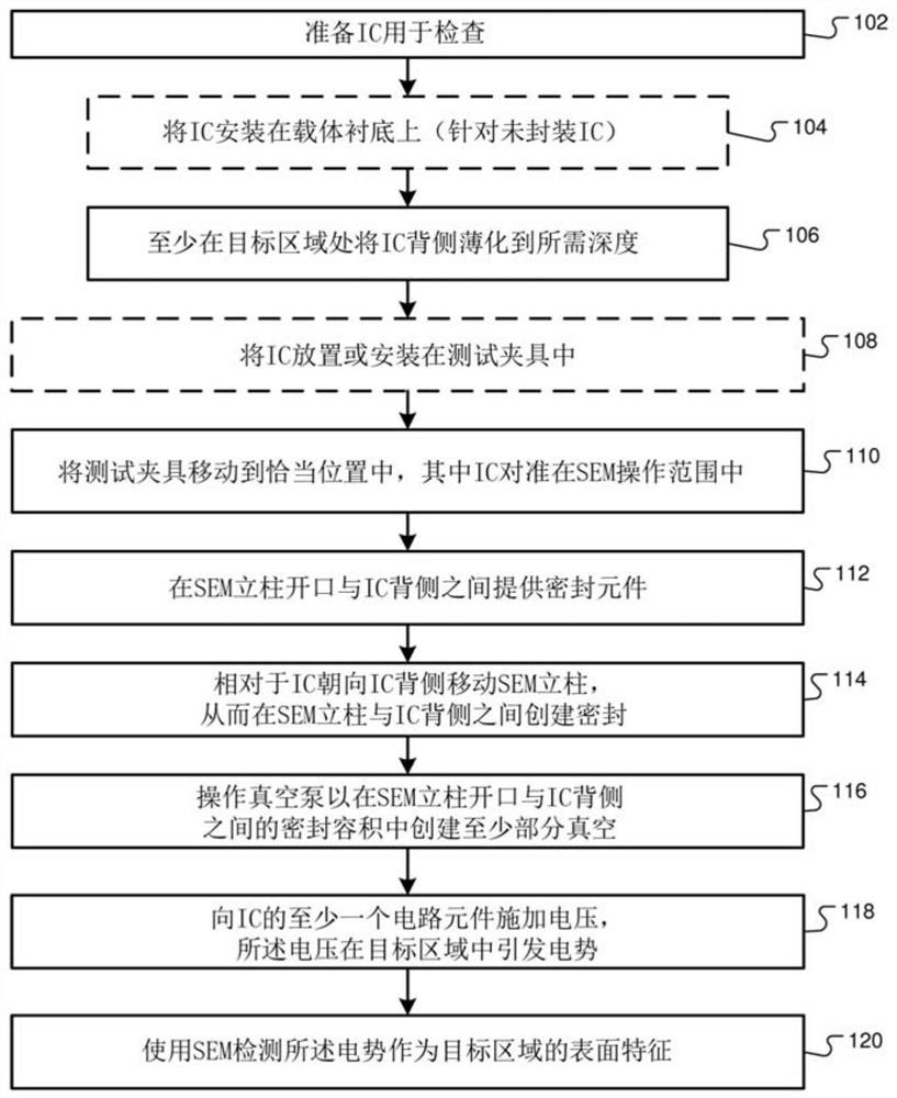
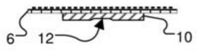
[0021] The present invention describes a new method for failure analysis in IC semiconductor devices. Several system designs and methods are provided to achieve a device under test (DUT) while it is being electrically stimulated by an automated test equipment (ATE) tester or while the device is on its own or mounted in a circuit board or other module. Electron beam (e-beam) technology is used to probe the transistors contained within the IC DUT, its dopant wells and their auxiliary connections while active within the host system. The DUT may be a packaged IC, or it may exist in unpackaged form, including as part of an overall fabricated wafer. Existing electron beam probing systems require the DUT to be placed in a high vacuum environment. The designs and methods herein seek to avoid the need to place the DUT in a high vacuum and instead use an environmental scanning electron microscope (ESEM) or a low vacuum SEM, where the DUT can be in a relatively low ("bad") vacuum enviro...


PUM


Abstract

The present invention provides new techniques for failure analysis in IC semiconductor devices, including methods for conducting electrical stimulation while a device under test (DUT) is being electrically stimulated or while the device is on its own or mounted in a circuit board or other module System design and methodology for implementing circuit probing using electron beam technology within an IC device under test (DUT) while simultaneously performing activities within a host system. The DUT may be a packaged IC or an IC in some unpackaged form. To create a localized evacuated volume immediately outside the electron beam tool, a sealing element is sealed against or around the DUT to obtain a localized seal. Such an arrangement eliminates the need for vacuum feedthroughs to the potentially thousands of signals required to operate and monitor the DUT, and further enables the DUT to be placed in its normal environment (such as mounted on a circuit board in its system) or The DUT is probed while operating on an error-free tester.

Description

technical field [0001] The present invention relates to integrated circuit (IC) diagnostics, characterization and modification using charged particle beams. Background technique [0002] Electrical fault analysis finds electrical problems throughout the IC device under test (DUT). Node reduction, new materials and more complex structures are driving new fault-finding techniques and improvements in system solutions for detecting faults. [0003] E-beam diagnostic systems are powerful tools for IC characterization and debug applications. For example, electron beam diagnostic systems are used for secondary electron imaging, circuit navigation using built-in computer automation design (CAD) displays, and voltage measurements from active circuits using voltage contrast principles. (See, eg, US Patent No. 4,706,019.) Other electron beam diagnostic systems use electrons in the beam to affect the signal used to detect faults. Such systems include Electron Beam Induced Current (EB...

Claims


Application Information

Patent Timeline
Patent Type & Authority Patents(China)
IPC IPC(8): G01R31/28
CPCG01R31/26H01J2237/0245H01J2237/162H01J37/28H01J2237/24564G01R31/307G01R31/3025H01J37/18H01J37/20H01J37/244H01J2237/2006H01J2237/2448
Inventor Y·博布罗夫C·A·坎波基亚罗
Owner FEI CO
Why Eureka
Try Eureka