Multi-objective angle ambiguity resolving method based on rotating interferometer

A rotating interferometer and angle ambiguity technology, applied in the field of data processing, can solve problems such as angle ambiguity, ambiguity, and algorithm failure, and achieve the effect of reducing the signal-to-noise ratio, reducing system complexity, and being easy to implement in engineering

Active Publication Date: 2018-07-06
XIDIAN UNIV
View PDF6 Cites 14 Cited by
  • Summary
  • Abstract
  • Description
  • Claims
  • Application Information

AI Technical Summary

Problems solved by technology

[0003] For the traditional processing method: (1) single-star angle measurement positioning, its advantage is that the system is easy to implement, but due to the limitation of antenna aperture and load, the direction finding accuracy is not high, and long-term observation is required, and the positioning accuracy of high-speed moving targets is relatively low. Poor, unable to locate short-term targets
(2) The phase interferometer direction finding technology has the advantages of high precision, real-time performance, and low system complexity. However, this method has the contradiction between the unambiguous viewing angle range and the angle measurement accuracy. The longer the baseline, the higher the angle measurement accuracy. produces more blur
(3) The traditional angle measurement and defuzzification algorithm based o

Method used


Image

  • Multi-objective angle ambiguity resolving method based on rotating interferometer
  • Multi-objective angle ambiguity resolving method based on rotating interferometer
  • Multi-objective angle ambiguity resolving method based on rotating interferometer

Examples


Embodiment 1

[0035]There are problems in the existing spaceborne passive direction finding technology: the traditional interferometer direction finding system can only estimate the two-dimensional angle information of a single target or multiple targets with frequency difference or time difference, and cannot estimate multiple targets working at the same frequency and at the same time For the two-dimensional angle information of the signal, the direction-finding system of the interferometer requires high accuracy of the phase difference between the array elements. In order to obtain an estimation result with a small error, a high signal-to-noise ratio is required; the traditional array direction-finding method can solve the multi-target problem , but to achieve the two-dimensional direction finding of the target, more array elements are required. Due to the load limitation, the number of array elements in the spaceborne array is small, and the aperture of the array is small, so the performan...

Embodiment 2

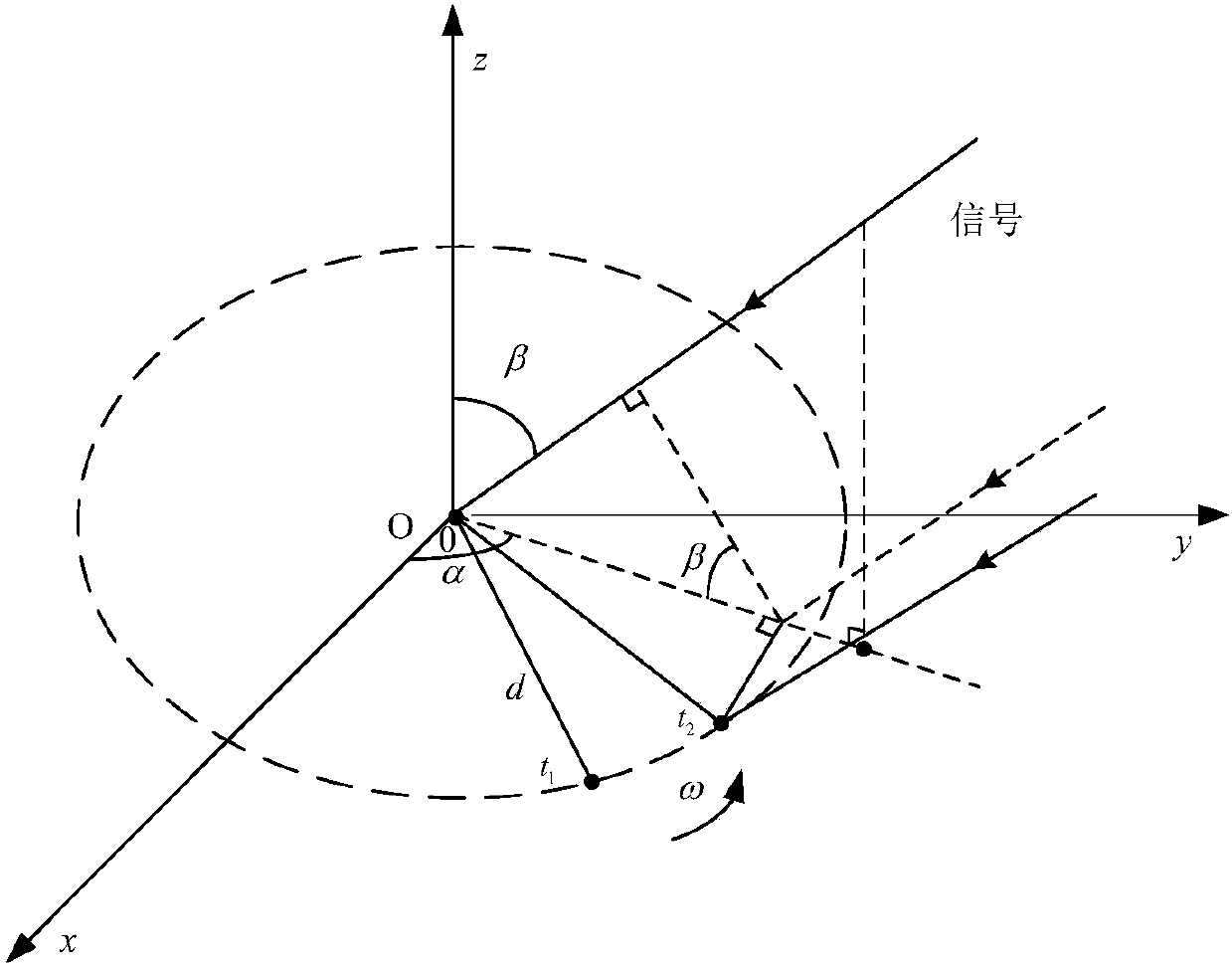
[0051] The multi-target angle defuzzification method based on the rotating interferometer is the same as in embodiment 1, wherein the phase difference matrix Φ(t) between the rotating interferometer array elements in step (1) is expressed as follows:

[0052]

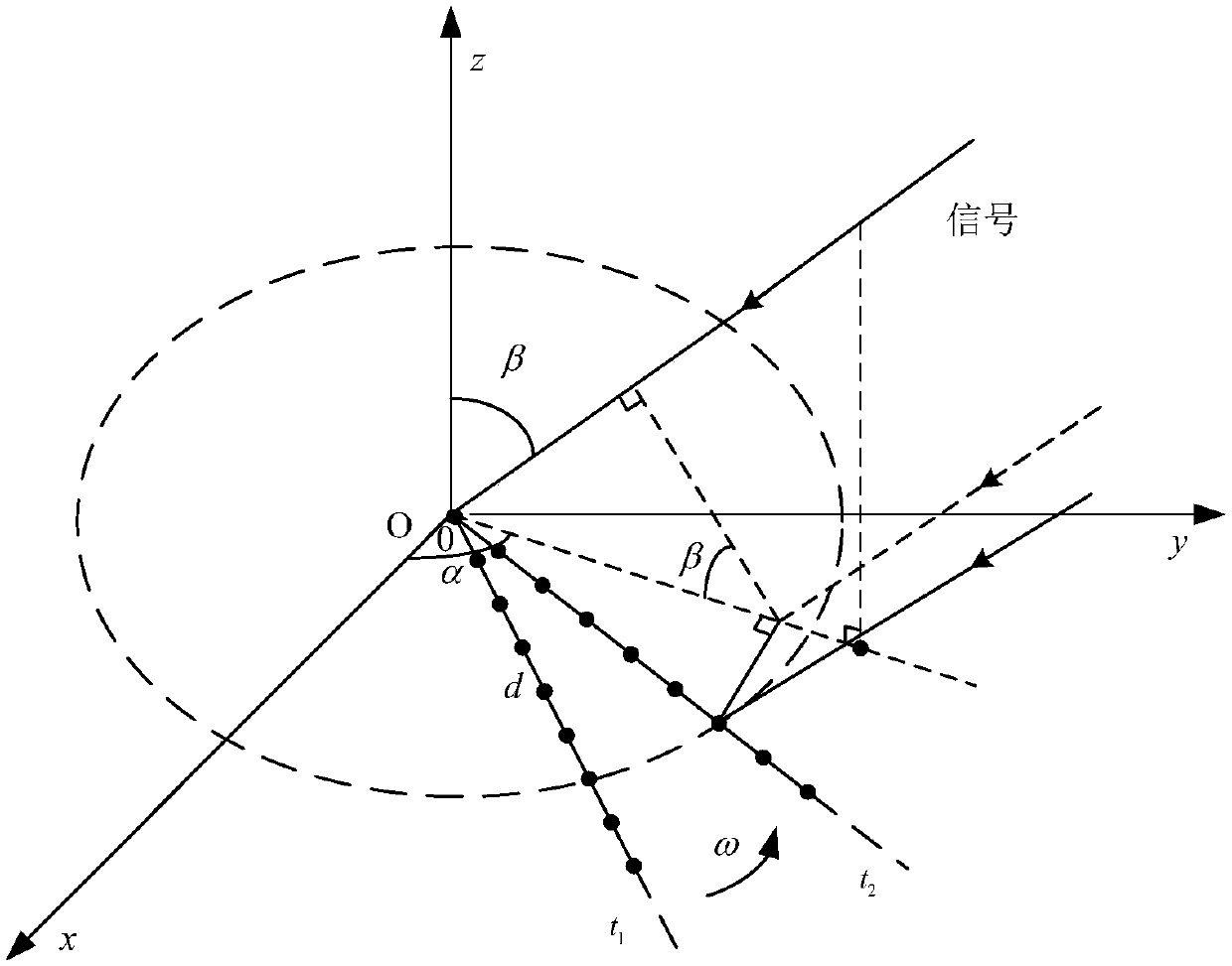
[0053] Among them, N is the number of interferometer array elements, L is the number of signals in the space, d is the array element spacing, and d>>λ / 2. ω is the angular velocity of the rotating interferometer moving around the first array element in the xOy plane along the counterclockwise uniform circular motion, α 1 ,α 2 ,...,α L ,β 1 ,β 2 ,...,β L are the azimuth angle and elevation angle of each signal respectively, and the signal wavelength is λ. The sampling frequency is f s , the value of t is

[0054] The invention establishes a multi-channel rotating interferometer system. Compared with the two channels of the traditional rotating interferometer, multiple array element channels are added, and the ...

Embodiment 3

[0056] The multi-target angle defuzzification method based on the rotating interferometer is the same as that in Embodiment 1-2, wherein the interference data matrix X received by the multi-channel rotating interferometer at time t in step 2 0 (t), expressed as follows:

[0057]

[0058] Write the above formula as:

[0059] x 0 (t)=Φ(t)S(t)+N(t)

[0060] where x 1 (t), x 2 (t),...,x N (t) is the data received by each array element, s 1 (t),s2 (t),...,s L (t) is the carrier frequency of each space signal, n 1 (t),n 2 (t),...,n N (t) is the Gaussian white noise of each array element channel, which obeys the normal distribution N(0,σ 2 ). x 0 (t) is the received data vector obtained by array sampling, and Φ(t) is an N×L-dimensional phase difference change matrix. S(t) represents the spatial signal, and N(t) represents the noise matrix.

[0061] The present invention uses the mid-spectrum estimation processing method of the array signal in the processing method, s...


PUM

PropertyMeasurementUnit
Snraaaaaaaaaa

Abstract

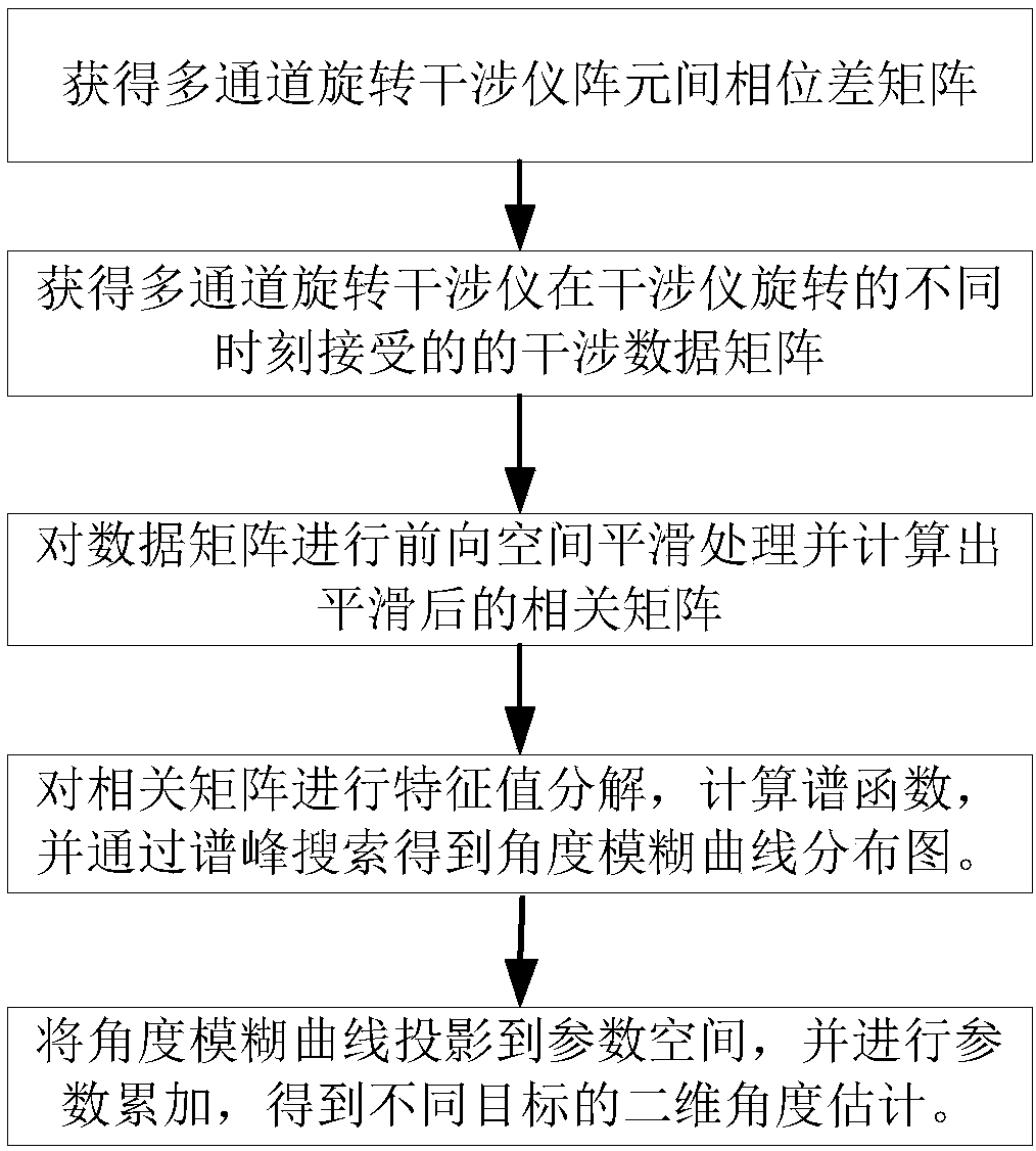
The invention discloses a multi-objective angle ambiguity resolving method based on a rotating interferometer. The multi-objective angle ambiguity resolving method mainly solves the problem that two-dimensional angle estimation of multi-objective signal sources working at the same frequency and same time cannot be solved in the prior art. The multi-objective angle ambiguity resolving method is implemented by the steps of: acquiring a phase difference matrix between array elements of a multichannel rotating interferometer; acquiring interference data matrixes received by the multichannel rotating interferometer at different moment during the rotation process; performing forward spatial smoothing processing on the data matrixes, and calculating smoothed signal autocorrelation matrixes; performing eigenvalue decomposition on the autocorrelation matrixes, calculating a spectral function, and acquiring an angle ambiguity curve distribution diagram through spectrum peak searching; and projecting angle ambiguity curves into a parameter space, and accumulating parameters to obtain two-dimensional angle estimation of different objectives. The multi-objective angle ambiguity resolving methodcan simultaneously resolve ambiguity of two-dimensional angles of different objectives, calculates unambiguous two-dimensional angle information of each objective, and is used for estimating two-dimensional angles of satellite-borne rotating interferometers in space electronic reconnaissance.

Description

technical field [0001] The invention belongs to the technical field of data processing, and in particular relates to a multi-target angle defuzzification method based on a rotating interferometer, which can be used for two-dimensional angle estimation of a spaceborne rotating interferometer, and further for space electronic reconnaissance. Background technique [0002] With the growth of demand and the development of science and technology, electronic reconnaissance satellites have become an important means of obtaining various intelligence, and have an irreplaceable position in modern warfare. Target location is an important application of electronic reconnaissance satellite, and the target position obtained by it is one of the most important information in reconnaissance information. How to improve the positioning accuracy is the key to the target positioning system. [0003] For the traditional processing method: (1) single-star angle measurement positioning, its advanta...

Claims


Application Information

Patent Timeline
IPC IPC(8): G01S5/06
CPCG01S5/06
Inventor 廖桂生杨志伟申皓明
Owner XIDIAN UNIV
Why Eureka
Try Eureka