
Double-L-shaped rectangular steel box type composite shear wall

A combined shear wall and shear wall technology, applied in the direction of walls, building materials, building components, etc., can solve the problems that the assembly quality of vertical components is not easy to guarantee, restricts the promotion of steel structure houses, and is prone to problems in transportation and installation. Achieve the effect of simple construction, excellent mechanical performance and superior mechanical performance

Pending Publication Date: 2018-07-10
GUANGDONG PROVINCIAL ACAD OF BUILDING RES GRP CO LTD +1
View PDF5 Cites 0 Cited by
  • Summary
  • Abstract
  • Description
  • Claims
  • Application Information

AI Technical Summary

Problems solved by technology

[0003] Prefabricated buildings are mainly divided into prefabricated concrete structures and prefabricated steel structures. Prefabricated concrete structure shear wall buildings have flexible layout and can provide better indoor space. However, because the assembly quality of vertical components is not easy to guarantee, the integrity is relatively Poor pouring structure, transportation and installation are prone to problems and other current constraints, and the promotion and application are limited to a certain extent
The prefabricated steel structure has a high assembly rate, energy saving and environmental protection, but in view of the impact of cost and cost, most high-rise residential buildings in my country currently use reinforced concrete shear wall structures, and corrosion and fire prevention also restrict the promotion of steel structure residential buildings

Method used


Image

  • Double-L-shaped rectangular steel box type composite shear wall
  • Double-L-shaped rectangular steel box type composite shear wall
  • Double-L-shaped rectangular steel box type composite shear wall

Examples


Embodiment 1

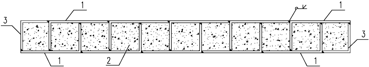
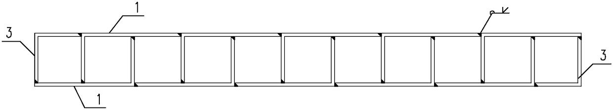
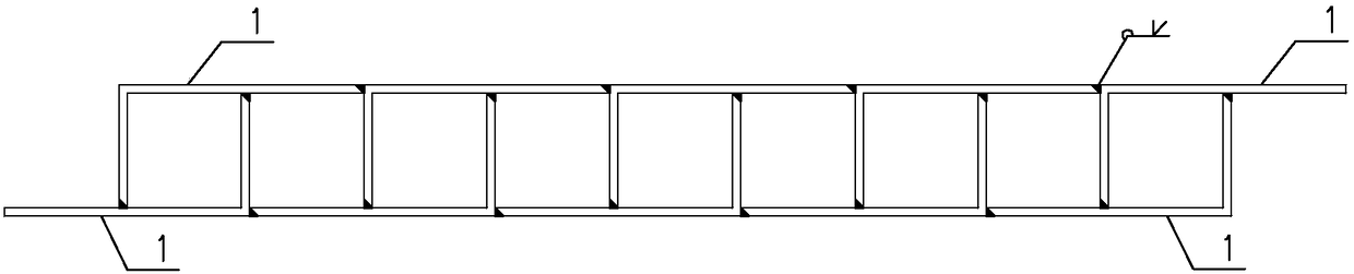
[0042] The embodiment of double L-shaped rectangular steel box type combined shear wall of the present invention is as follows Figure 1 to Figure 7 As shown, the shear wall includes a steel box skeleton. The steel box skeleton includes a plurality of internode units arranged continuously. Adjacent internode units are welded. Each internode unit consists of two pairs of identical structures. The right-angle steel plate 1 is welded. The right-angle steel plate 1 is L-shaped. Two right-angle steel plates 1 form a double-L shape, that is, each internode unit is a double-L-shaped assembly composed of two L-shaped right-angle steel plates. The right-angle steel plate 1 There are long right-angled sides 11 and short right-angled sides 12, and the length of the long right-angled sides 11 is 2 times of the length of the short right-angled sides 12. The short right-angled sides 12 of 1 are welded together, and the welding place between the short right-angled side 12 and the long right-...

Embodiment 2

[0046] Embodiment two of the double L-shaped rectangular steel box type combined shear wall of the present invention is as Figure 8 to Figure 11 As shown, the difference from Embodiment 1 is that the shear wall is an L-shaped wall, and the sealing plate includes an equilateral L-shaped end plate 3 with two equal-length right-angled sides and a straight steel plate 4, and the L-shaped end plate 3 Set at the wall end position and the wall corner position, the inline steel plate 4 is arranged in the wall corner position, the side length of the L-shaped end plate 3, and the length of the inline steel plate 4 are equal to the length of the short right-angled side 12, and the L-shaped end plate 3 It is welded with the adjacent right-angle steel plate 1, and the in-line steel plate 4 is welded with the adjacent L-shaped end plate 3 and the right-angle steel plate 1.

[0047] In this embodiment, the L-shaped end plate 3 is connected to the adjacent right-angle steel plate 1 by equal-...

Embodiment 3

[0049] Three examples of embodiment of double L-shaped rectangular steel box type composite shear wall of the present invention Figure 12 to Figure 14 As shown, the difference from Embodiment 1 is that the shear wall is a T-shaped wall, and the sealing plate includes an equilateral L-shaped end plate 3 with two equal-length right-angled sides and a straight steel plate 4, and the L-shaped end plate 3 Set at the wall end position, the inline steel plate 4 is arranged in the corner position of the wall, the side length of the L-shaped end plate 3, the length of the inline steel plate 4 are all equal to the length of the short right-angled side 12, the L-shaped end plate 3 and the adjacent The right-angle steel plate 1 is welded, and the in-line steel plate 4 is welded to the adjacent right-angle steel plate 1.

[0050] In this embodiment, the L-shaped end plate 3 is connected to the adjacent right-angle steel plate 1 by equal-strength groove welding, and the in-line steel plate...


PUM

PropertyMeasurementUnit
thicknessaaaaaaaaaa
thicknessaaaaaaaaaa

Abstract

The invention discloses a double-L-shaped rectangular steel box type composite shear wall comprising a steel box framework. The steel box framework comprises a plurality of inter-section units which are arranged continuously, and the adjacent inter-section units are welded. Each inter-section unit is formed by welding two right-angle steel plates which are the same in structure and are arranged inpairs, wherein each right-angle steel plate is in an L shape and is provided with a long right-angle edge and a short right-angle edge, and the length of the long right-angle edge is twice the lengthof the short right-angle edge. When each pair of right-angle steel plates are welded, the long right-angle edge of one right-angle steel plate is welded with the short right-angle edge of the other right-angle steel plate, and the welding part of the short right-angle edge and the long right-angle edge is located on the center line of the long right-angle edge. Sealing plates are further welded at the exposed parts of the welded inter-section units, so that the steel box framework becomes a closed structure with a plurality of inner cavities, the cross section of each inner cavity is square,and concrete is poured in each inner cavity. The steel amount for the shear wall is economical, the construction is rapid, and the advantages of concrete and steel structures can be brought into fullplay.

Description

technical field [0001] The invention belongs to a prefabricated combined structure system in civil engineering, specifically a double L-shaped rectangular steel box combined shear wall, which can be used in common high-rise buildings, especially suitable for prefabricated houses and apartments middle. Background technique [0002] Traditional housing construction technology has low production efficiency, slow construction speed, long construction period, high material consumption and high labor intensity. These series of conditions can no longer meet the rigid demand for housing in modern society. The prefabricated building has the following characteristics: ①The design is diversified and can be designed according to the housing requirements; ②The function is modernized, and a variety of new materials such as energy saving and environmental protection can be used; ③Manufacturing is factory-based, which can make the building components and accessories uniform and factory-made...

Claims


Application Information

Patent Timeline
Patent Type & Authority Applications(China)
IPC IPC(8): E04B2/00E04C2/28
CPCE04B2/00E04C2/28E04C2/46
Inventor 曹大燕杨仕超徐其功陈林李俞谕苍久山刘翔何文辉刘春艳李昂朱梓健徐翩翩
Owner GUANGDONG PROVINCIAL ACAD OF BUILDING RES GRP CO LTD
Learn More