A suction type slag cleaner

A kind of slag cleaning machine and suction technology, applied in construction, infrastructure engineering, sheet pile walls, etc., can solve problems such as inaccessible, difficult to clean holes thoroughly, complicated installation and disassembly, etc.

Active Publication Date: 2020-04-14
任国勇
View PDF1 Cites 1 Cited by
  • Summary
  • Abstract
  • Description
  • Claims
  • Application Information

AI Technical Summary

Problems solved by technology

The cleaning effect of this slag cleaning method is obvious. Since the equipment used is relatively large and the installation and disassembly are complicated, it is usually only used for secondary hole cleaning.
This method uses the buoyancy of the mud at the bottom to discharge the sediment. Therefore, when the mud concentration is low or the diameter of the sediment block is large, it is difficult to clean the hole thoroughly.
[0007] The above three hole cleaning methods all use the suspension of mud to clean the drilling slag, but for the slag cleaning of the mud concentration is low or even the clear water hole, the slag cleaning progress is slow, and the slag cleaning is not thorough, and the relevant requirements cannot be met.
In addition, for some situations where slag falls in the follow-up work (such as lowering the steel cage) after the hole cleaning operation has been completed, all existing secondary hole cleaning measures cannot really solve the problem.

Method used


Image

  • A suction type slag cleaner
  • A suction type slag cleaner
  • A suction type slag cleaner

Examples


Embodiment 1

[0038] Embodiment 1: refer to Figure 1 to Figure 4 shown;

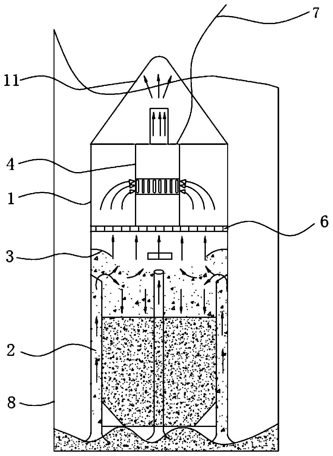
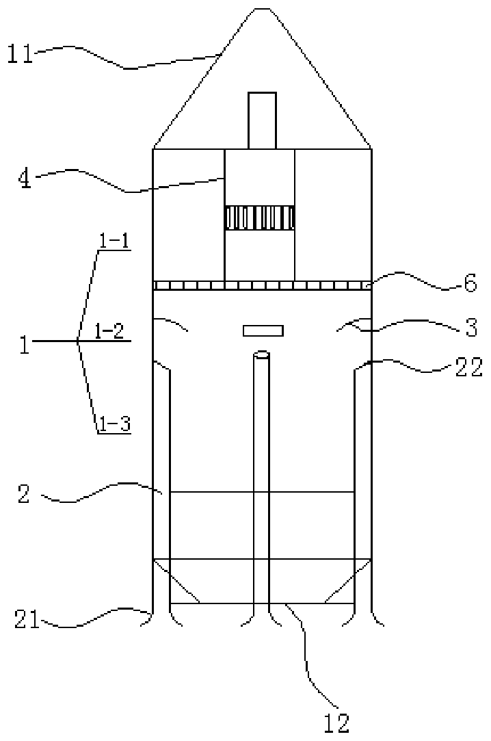
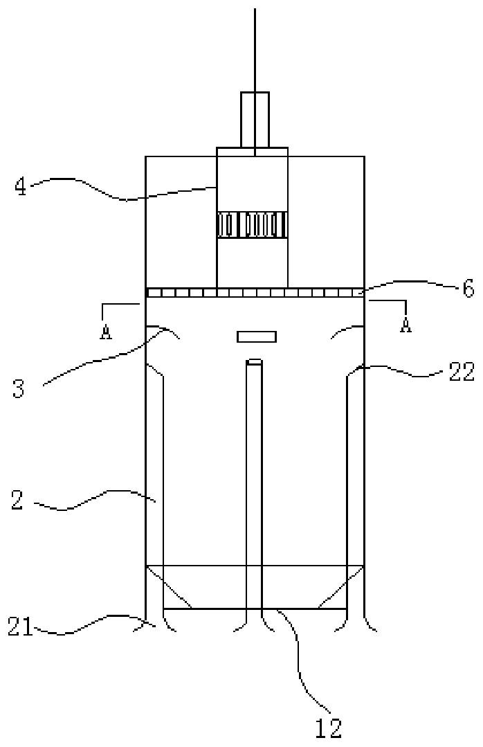
[0039] A suction type slag cleaner, comprising: a closed cylinder 1, a slag suction device 4 and at least one slag suction pipe 2.

[0040] Specifically, a boom 11 is fixedly installed on the top of the cylinder 1 for lifting and lowering the cylinder 1, and a sealed slag outlet 12 is provided at the bottom of the cylinder 1; It is installed in the cylinder body 1 in the direction, the inlet end protrudes from the bottom of the cylinder body 1, and the outlet end is arranged in the cylinder body 1; the slag suction device 4 is installed on the side above the outlet end of the slag suction pipe 2 for producing cylinder The negative pressure suction in the body 1 and the slurry after the separation of the sludge-serum mixture is sucked and discharged; the sediment-slurry mixture in the borehole / well 8 is diffused into the cylinder through the slag suction pipe 2 under the suction of the slag suction device 4, The sed...

Embodiment 2

[0052] The structure of embodiment 2 is similar to embodiment 1, with reference to Figure 5 , the difference is that:

[0053] The cylinder body 1 is equipped with at least one slurry discharge pipe 5 axially, the top of the slurry discharge pipe 5 communicates with the outlet end of the slag suction device 4, and the bottom end of the slurry discharge pipe 5 protrudes from the cylinder body 1. Preferably, A slurry discharge pipe 5 is installed on the central axis of the cylinder body 1 .

[0054] The slurry discharged from the discharge port of the slag suction device 4 is discharged to the center of the borehole / well 8 through the slurry discharge pipe 42, which can fully mix the sludge and the slurry, thereby increasing the cleaning speed of the sludge.

Embodiment 3

[0056] The structure of embodiment 3 is similar to that of embodiment 1, the difference is that the slag suction device 4 is driven by a built-in battery.

[0057] In this way, it is convenient to use in the field and in areas where power supply is inconvenient, so that the use of the suction slag cleaner is more convenient, safer and more extensive.


PUM


Abstract

The invention provides a sucking-in type slag removing machine. The sucking-in type slag removing machine comprises a closed barrel body, at least one slag sucking pipe and a slag sucking device; a hoisting arm is installed on the top of the barrel body; the bottom segment of the barrel body is provided with a sealed slag outlet; the slag sucking pipe is installed in the barrel body in the axial direction of the barrel body; the inlet end of the slag sucking pipe stretches out of the bottom of the barrel body, and the outlet end of the slag sucking pipe is arranged in the barrel body; the slagsucking device is installed above the side portion of the outlet end of the slag sucking pipe, and is used for generating negative pressure sucking force in the barrel body and sucking and discharging slurry after a sediment-slurry mixture is separated; the sediment-slurry mixture in a drill hole / well enters the barrel body to be dispersed under the effects of the sucking force of the slag sucking device; sediment falls into the bottom segment of the barrel body, and the slurry is discharged outwards by the slag sucking device to be circulated. The sucking-in type slag removing machine belongs to an active slag removing manner, the slag removing machine can be used for removing large-particle-diameter stone slag and can also be used for removing slag in slurry holes and clean water holes,slag removing can be performed even though mud making and slag mixing are not needed, and the sucking-in type slag removing machine is high in slag removing effect and wide in using range.

Description

technical field [0001] The invention relates to the technical field of concrete pouring pile foundation construction in construction and traffic engineering and the field of well bottom dredging, in particular to a suction-type slag cleaner for removing sediment at the bottom of pile holes and silted sediment at the bottom of well holes. Background technique [0002] In the construction of the concrete pouring pile foundation project, whether it is the pile foundation drilling operation or the hole cleaning operation before pouring concrete, it is necessary to remove a large amount of sediment formed at the bottom of the pile hole. The cleaning method of the hole bottom directly determines the operation efficiency and cleaning. Therefore, it is very important to choose cleaning methods and cleaning tools scientifically and reasonably. In addition, similar problems are also faced in the operation of cleaning up the silt accumulated at the bottom of the wellbore. [0003] At ...

Claims


Application Information

Patent Timeline
Patent Type & Authority Patents(China)
IPC IPC(8): E02D13/08
CPCE02D13/08
Inventor 任国勇
Owner 任国勇
Why Eureka
Try Eureka