Focus-moving type CT machine, scanning method and image reconstruction method

A focus, tomographic scanning technology, applied in image data processing, computer tomography scanners, 3D image processing, etc. The effect of focus stabilization, good isotropic resolution effect

Active Publication Date: 2018-07-17
沈阳晟诺科技有限公司
View PDF10 Cites 5 Cited by
  • Summary
  • Abstract
  • Description
  • Claims
  • Application Information

AI Technical Summary

Problems solved by technology

[0011] Embodiments of the present invention provide a computerized tomography device, method, and imag...

Method used


Image

  • Focus-moving type CT machine, scanning method and image reconstruction method
  • Focus-moving type CT machine, scanning method and image reconstruction method
  • Focus-moving type CT machine, scanning method and image reconstruction method

Examples


Embodiment 1

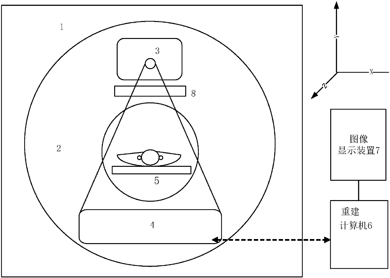
[0075] Such as Figure 1-2 As shown, a computed tomography device provided by an embodiment of the present invention includes a fixed frame 1, a rotating frame 2, a light source generating device 3, a signal detection device 4, a scanning target supporting device 5, and a light source collimating device 8; The rotating frame 2 can rotate around a fixed point on the X-Y plane; the scanning target supporting device 5 is fixed along the Z direction to meet the tomographic scanning trajectory, and the X-Y-Z coordinate system meets the definition of the right-handed system; the light source generating device 3 is installed on the On the rotating frame 2, the scanning light of the cone beam can be output, and the focus moves continuously along the Z direction; the signal detection device 4 is installed on the rotating frame 2, opposite to the light source generating device 3, and During the rotation process, the relative position with the light source generating device 3 does not ch...

Embodiment 2

[0083] Such as image 3 As shown, the embodiment of the invention also provides a scanning control method using any one of the computer tomography devices described above, wherein the computer tomography device will not be described again. The scan control method may include the following steps:

[0084] S101: The light source generating device and the signal detecting device rotate and scan in the X-Y plane to meet the tomographic scanning trajectory;

[0085] S102: When the tomographic scan is started, the position of the focus of the light source generating device on the anode target surface is continuously changed, and the focus position is continuously moved along the Z direction according to a predetermined track;

[0086] S103: The radiation shielding unit A and the radiation shielding unit B are translated along the Z direction under the control of the drive motor, and the displacement changes satisfy:

[0087] ΔA z =ΔB z =Δz (1)

[0088]The collimator is composed...

Embodiment 3

[0107] Such as image 3 As shown, the embodiment of the present invention also provides a method for image reconstruction based on the data obtained by any of the scanning control methods described above, the CT machine adopts the CT machine as described in Embodiment 1, and the scanning method is as in the embodiment 2 and will not be repeated here. And the method for performing image reconstruction on the data obtained by the scanning control method comprises the following steps:

[0108] S201: Perform necessary preprocessing on the scanned data;

[0109] S202: rearranging the data preprocessed in the above step S201;

[0110] S203: Filter and weight the data rearranged in the above step S202;

[0111] S204: Back-project the filtered and weighted data in the above step S203;

[0112] S205: Post-processing the back-projected data in step S204 above to obtain an image that can be used for diagnosis.

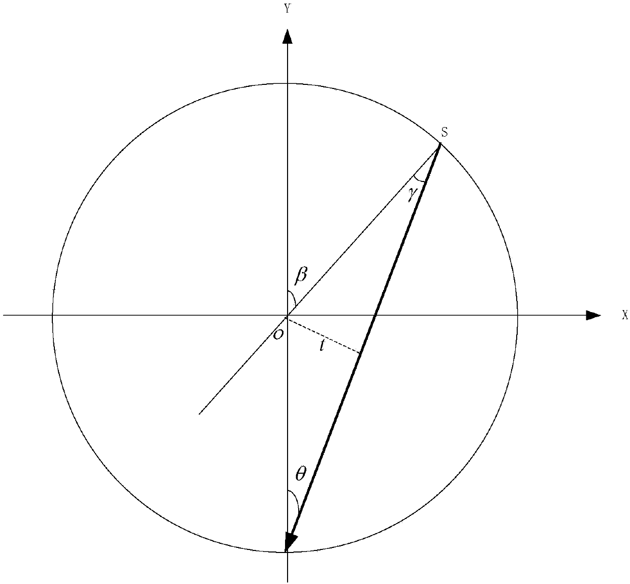
[0113] Further, the step S202 includes:

[0114] β is the projection a...


PUM


Abstract

According to the embodiment, the invention relates to a computed tomography device, which comprises a fixed frame (1), a rotary frame (2), a light source generating device (3), a signal detection device (4) as well as a scanned object supporting device (5) and a light source collimation device (8), wherein the rotary frame (2) can rotate around some fixed point in an X-Y plane; the light source generating device (3) is arranged on the rotary frame (2), and scanning light of a cone beam can be outputted and a focus can do continuous movements in an Z direction; the signal detection device (4) is arranged on the rotary frame (2) and is fixed relative to the position of the light source generating device (3); the signal detection device (4) is of an area-array structure adaptive to collectionof the cone beam, and the signal detection device comprises a plurality of light sensing elements; and the light source collimation device (8) can do translation in the Z direction along with the change in a focus position of the light source generating device (3).

Description

technical field [0001] The invention relates to the technical field of medical computed tomography, in particular to a new dynamic focus control mode of an X light source and a corresponding image reconstruction method in a tomographic scanning mode, and a CT machine using the scanning mode and reconstruction method. Background technique [0002] CT (Computed Tomography), also known as computerized tomography equipment. With the maturity and development of technologies such as area array detectors and cone beam reconstruction methods, the data acquisition method of CT machines has developed from the fan-beam acquisition method composed of single-layer detector physical units to the cone-beam acquisition method composed of multi-layer detector physical units. Way. The imaging mode of CT machine has also gradually developed from the traditional single-slice and two-dimensional imaging method, that is, imaging in the rotation plane (here referred to as the X-Y plane), to a thr...

Claims


Application Information

Patent Timeline
IPC IPC(8): A61B6/03G06T15/00
CPCA61B6/032A61B6/4021A61B6/42A61B6/52G06T15/005
Inventor 不公告发明人
Owner 沈阳晟诺科技有限公司
Why Eureka
Try Eureka