Thrust foil dynamic pressure air bearing with thick top foil structure

An air bearing and foil technology, which is applied in the field of thrust foil dynamic pressure air bearings, can solve the problems of weakening the wedge-shaped air film compression effect, reducing the bearing capacity, and insufficient thickness of the top layer of foil, etc., and achieves the requirement of reducing the consistency accuracy , Improve the bearing capacity and solve the effect of foil deformation

Active Publication Date: 2018-07-17
SHIJIAZHUANG KINGSTON BEARING TECH
View PDF14 Cites 40 Cited by
  • Summary
  • Abstract
  • Description
  • Claims
  • Application Information

AI Technical Summary

Problems solved by technology

At present, the thickness of the top foil of the thrust foil gas bearing is mostly 0.1mm-0.2mm. In order to improve the performance of the bearing, the accuracy of the processing consistency of the support wave foil must be improved, which increases the complexity of the process and the processing cost; at the s...

Method used


Image

  • Thrust foil dynamic pressure air bearing with thick top foil structure
  • Thrust foil dynamic pressure air bearing with thick top foil structure
  • Thrust foil dynamic pressure air bearing with thick top foil structure

Examples


Embodiment Construction

[0016] The present invention will be further described below in conjunction with the accompanying drawings and specific embodiments.

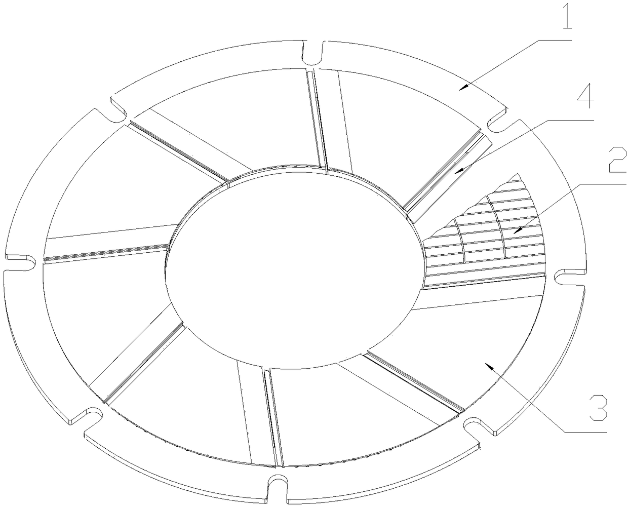
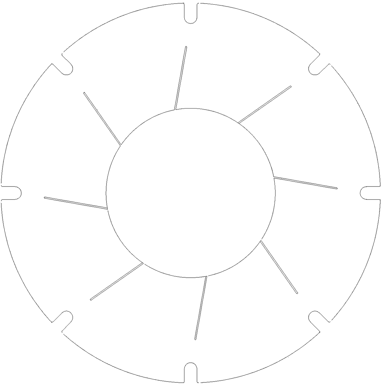
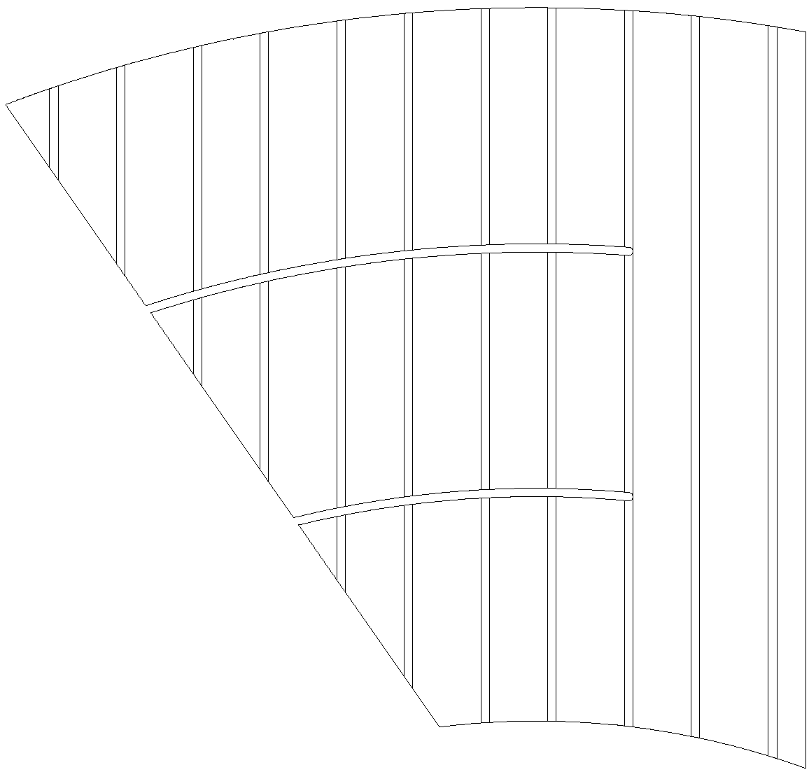
[0017] Specific examples, such as Figure 1 to Figure 4 As shown, a thrust foil dynamic pressure air bearing with a thick top-layer foil structure includes a bottom plate 1, a supporting corrugated foil 2 and a top-layer foil 3. The circular bottom plate 1 is arranged below, and multiple fan-shaped top-layer foils The sheet 3 is fixed above the bottom plate 1, and the supporting corrugated foil 2 is assembled between the bottom plate 1 and the top layer foil 3, and also includes an inlet segment gasket 4 arranged on the radial side of the junction of the top layer foil 3 and the bottom layer 1, and the inlet The thickness of the segment gasket 4 is adjustable, the thickness of the top layer foil 3 is 0.5mm-1mm, and it is processed by mold hydroforming. The deformation is 0.01mm-0.02mm, the inlet section gasket 4 and the bottom plate 1, the top...


PUM

PropertyMeasurementUnit
Thicknessaaaaaaaaaa
Deformationaaaaaaaaaa
Flatnessaaaaaaaaaa

Abstract

The invention relates to a thrust foil dynamic pressure air bearing with a thick top layer foil structure. The thrust foil dynamic pressure air bearing comprises a bottom plate (1), supporting wave foils (2) and top foil sheets (3), wherein the round bottom plate (1) are arranged on the lower part, the plurality of fan-shaped top foil sheets (3) are fixed above the bottom plate, and the supportingwave foils (2) are assembled on the bottom plate (1) and the top foil sheets (3); the bearing is characterized by further comprising inlet section gaskets (4) are arranged on one side in the radial direction of the joint of the top foil sheets (3) and the bottom plate (1), and the thickness of the inlet section gaskets (4) is adjustable; and the thickness of the top foil sheets is 0.5 mm to 1 mm,the support wave foils (2) and the top foil sheets are assembled in a pre-tightening mode, and the shape variable of the supporting wave foils is 0.01 mm-0.02mm. On one hand, the requirement for theconsistency precision of the foil bearing on the support wave foils is lowered, and meanwhile, the problem of foil deformation of the inlet sections of the top foil sheets of the thrust bearing is solved, so that the thickness shape of the gas film of the inlet section is basically unchanged, and the bearing capacity of the bearing is improved.

Description

technical field [0001] The invention relates to the technical field of air bearings, in particular to a thrust foil dynamic pressure air bearing with a thick top foil structure. Background technique [0002] Foil air bearing is a self-acting dynamic pressure air bearing using air as the lubricating medium. It was first applied in the environmental control system (ACM) of aircraft in the 1970s, and gradually extended to small turbojet engines in the 1980s and 1990s. In the 21st century, it has been further applied and developed in the fields of air suspension centrifugal blower, electronic turbocharger and hydrogen fuel cell compressor. Compared with traditional high-speed bearings, foil air bearings have the advantages of simple structure, high speed, low friction power consumption, high and low temperature resistance, good stability and convenient maintenance, etc., and have broad application prospects in the field of high-speed rotating machinery in the future. [0003] T...

Claims


Application Information

Patent Timeline
IPC IPC(8): F16C17/08F16C33/12F16C33/14
CPCF16C17/08F16C33/12F16C33/14Y02E10/20
Inventor 李微马存秦懂朱建军何波
Owner SHIJIAZHUANG KINGSTON BEARING TECH
Why Eureka
Try Eureka