Coating machine capable of reducing air pollution

An air pollution and spraying machine technology, applied in the field of spraying machines that can reduce air pollution, can solve problems such as polluted environment and health damage of workers, and achieve the effects of reducing pollution, improving working environment and convenient operation.

Inactive Publication Date: 2018-07-20
河南胜泽建筑保温工程有限公司
View PDF7 Cites 2 Cited by
  • Summary
  • Abstract
  • Description
  • Claims
  • Application Information

AI Technical Summary

Problems solved by technology

[0005] The invention overcomes the deficiencies of the prior art, provides a spraying machine that can effectively deal with the dispersed paint mist in the spraying process, and solves the problems of polluting the environment and causing damage to the health of workers when the spraying machine is in use

Method used


Image

  • Coating machine capable of reducing air pollution

Examples


Embodiment 1

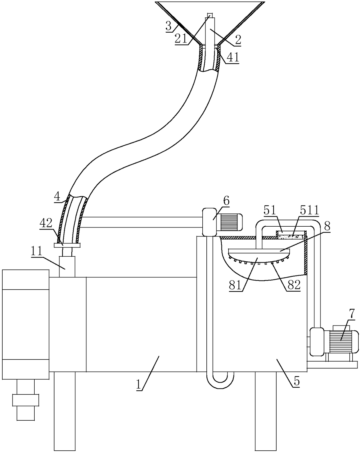
[0025] A spraying machine capable of reducing air pollution, comprising a spraying machine main body 1, a screw pump 11 is connected to the spraying machine main body 1, a spraying pipe 2 is connected to the outlet of the screw pump 11, and a spray nozzle 21 is connected to the end of the spraying pipe 2. The spray nozzle 21 is covered with an umbrella cover 3, and the umbrella cover 3 is connected with an exhaust pipe 4; a water tank 5 is installed on the main body 1 of the spraying machine, an exhaust port 51 is arranged on the water tank 5, and an exhaust fan is installed on the water tank 5 6. The air inlet of the exhaust fan 6 communicates with the exhaust pipe 4 through a pipeline, and the air outlet of the exhaust fan 6 communicates with the water tank 5 through a pipeline.

[0026] Spray head 21 overcoat of the present invention is provided with umbrella cover 3, then in the spraying process, umbrella cover 3 can stop unnecessary paint mist from being diffused into the ...

Embodiment 2

[0028] On the basis of embodiment one, the exhaust pipe 4 is sleeved outside the spray pipe 2, and the end of the exhaust pipe 4 connected to the umbrella cover 3 is connected with a support frame 41 between the spray pipe 2, and the exhaust pipe 4 The other end is connected with a sealing plate 42, and the sealing plate 42 is fixed on the spraying pipe 2, and the pipeline connected to the air inlet of the exhaust fan 6 communicates with the end of the exhaust pipe 4 near the sealing plate 42.

[0029] Since the exhaust pipe 4 is sleeved on the spray pipe 2, in the process of using the present invention, the staff only need to pull a rope to extend the spray head 21 to the position to be sprayed, which is more convenient to operate and avoids exhaust. The case where the tube 4 is entangled and the paint mist cannot be discharged normally.

Embodiment 3

[0031] On the basis of Embodiment 1 or Embodiment 2, the pipe connected to the air outlet of the exhaust fan 6 is connected to the bottom of the water tank 5 .

[0032] The paint mist pumped by the exhaust fan 6 enters the water tank 5 from the bottom of the water tank 5, so that the paint mist can be fully mixed with the water in the water tank 5 to ensure that the paint mist can be more fully dissolved in the water and reduce the volatilization of the paint mist.


PUM


Abstract

The invention relates to the field of coating machines, in particular to a coating machine capable of reducing air pollution. According to the technical scheme, the coating machine comprises a coatingmachine body, a spiral pump is connected to the coating machine body, an outlet of the spiral pump is connected with a coating pipe, and a spray nozzle is arranged on the end portion of the coating pipe. The spray nozzle is sleeved with an umbrella-shaped cover, and the umbrella-shaped cover is connected with an exhaust pipe. The coating machine body is provided with a water tank, an exhaust opening is formed in the water tank, the water tank is provided with an exhaust fan, the air inlet of the exhaust fan is connected with the exhaust pipe through a pipeline, and an air outlet of the exhaust fan communicates with the water tank through a pipeline. The coating machine capable of reducing air pollution can effectively treat dispersed painting mist in the coating process, and the problemsthat environment is polluted and health of staffs is damaged when the coating machine is in use are solved

Description

technical field [0001] The invention relates to the field of spraying machines, in particular to a spraying machine capable of reducing air pollution. Background technique [0002] The spraying machine is a special coating equipment that adopts spraying technology. The principle is to control the air flow to instantly push the air distribution reversing device to change direction, so that the piston of the air motor makes a stable and continuous reciprocating motion. The inhaled paint is pressurized, and the paint is delivered to the spray gun through the high-pressure hose, and the paint is atomized by the spray gun and released to the surface of the object to be coated. The spraying machine is mainly composed of a feeding device, a spray gun, and an atomization source. [0003] The utility model patent with the patent application number CN201621065631.2 discloses a new type of spraying machine, including a spraying machine, a spray gun, a compressor and a cart. The discha...

Claims


Application Information

Patent Timeline
Patent Type & Authority Applications(China)
IPC IPC(8): B05B12/32B05B14/30
Inventor 马志涛
Owner 河南胜泽建筑保温工程有限公司
Why Eureka
Try Eureka