Shock-resistant assembly self-locking type rolling half grouting sleeve

A semi-grouting sleeve, self-locking technology, applied in the direction of structural elements, building components, building reinforcements, etc., can solve the problems of difficult processing, bulky sleeve shape, poor deformation resistance, etc., to control the quality of threaded connections, The effect of easy screw connection quality and reduction of rolling deformation

Inactive Publication Date: 2018-07-20
HEFEI CONSTR ENG GRP
View PDF12 Cites 1 Cited by
  • Summary
  • Abstract
  • Description
  • Claims
  • Application Information

AI Technical Summary

Problems solved by technology

The above two types of sleeves have their own disadvantages. Among them, the cast iron (steel) sleeve has a bulky appearance and high technical requirements, and the processing quality of the sleeve is difficult to guarantee; the machining sleeve is mainly made of steel rods or thick-walled steel pipes. The material is made by hollowing out the steel bar or milling the inner wall of the thick-walled steel pipe by mechanical milling. Although it is relatively strong, it is still relatively heavy, and the material consumption is large, the production cost is high, and the production efficiency is low.
[0004] Chinese patent document CN104563396A discloses a pier head extruded semi-grouting steel bar sleeve and connecting structure and CN102587586A discloses a new type of cement grouting thread composite steel bar connecting joint. The sleeve part is directly processed by hot-rolled seamless steel pipe or steel pipe. Compared with the milling process of solid steel rods, it has certain advantages, but there are still the following disadvantages: 1) The diameter of the sleeve at the non-grouting connection end is quite different from the diameter of the steel bar to be connected. 2) The grooves and / or convex ribs used for shear resistance inside the sleeve are made by rolling or spinning. In order to meet the requirements of JGJ107 standard I joints, the The wall thickness of the barrel is thicker, resulting in a bulky sleeve profile
[0005] To sum up, the currently disclosed grouting sleeves have disadvantages such as difficult processing, bulky form, high cost, and poor deformation resistance, and the existing technologies and processes are difficult to ensure that the steel bars to be connected can be connected coaxially, and it is difficult to ensure that the inside of the sleeve Grout dense

Method used


Image

  • Shock-resistant assembly self-locking type rolling half grouting sleeve
  • Shock-resistant assembly self-locking type rolling half grouting sleeve
  • Shock-resistant assembly self-locking type rolling half grouting sleeve

Examples


Embodiment 1

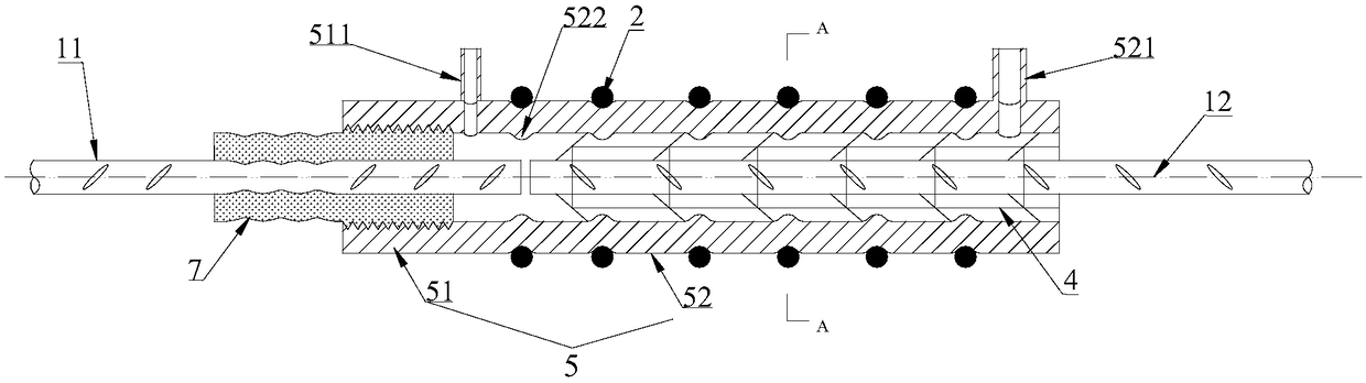
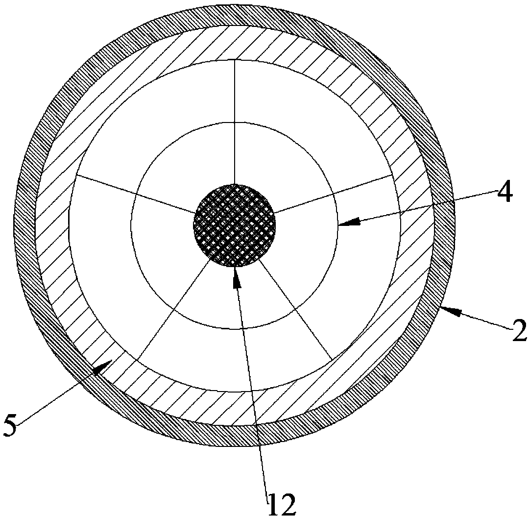
[0067] Such as figure 1 , figure 2 , image 3 As shown, an anti-seismic assembled self-locking rolling semi-grouting sleeve, including a sleeve 5, a steel pipe transition section 7, and a self-locking steel skeleton 4;

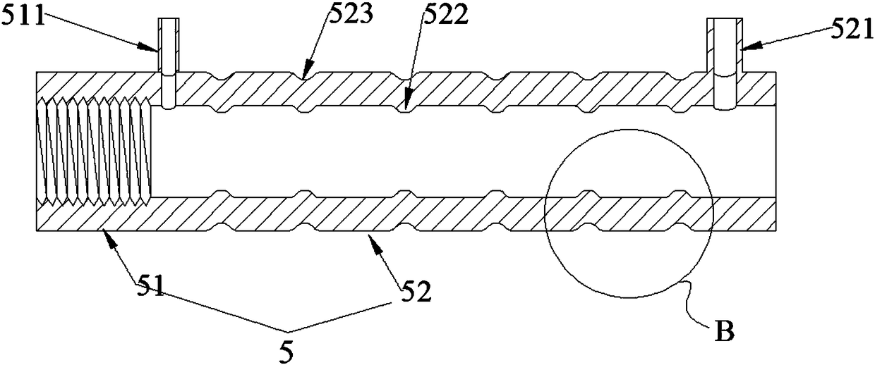
[0068] The sleeve 5 is made of seamless steel pipe, and the sleeve 5 includes a non-grouting connection section 51 and a grouting connection section 52; the grouting connection section 52 is processed by rolling to form grooves 523 on the outer wall and convex ribs 522 on the inner wall. Both ends of the grouting connection section 52 are provided with a grouting hole 521 and a vent hole 511 respectively, and the vent hole 511 is close to the non-grouting connection section 51. In order to ensure sufficient grouting, the present embodiment can also design the diameter of the vent hole 511 The diameter is smaller than the diameter of the grouting hole 521, so that the grouting amount is greater than the grouting amount, thereby ensuring that the grouting in ...

Embodiment 3

[0086] A processing method for fabricated concrete components, comprising the following steps:

[0087] Step 1. Binding of reinforced skeleton of prefabricated concrete members

[0088] One end of the first steel bar 11 to be connected is bound and fixed with other steel bars to form a reinforced skeleton of the fabricated concrete member. The other end of the first steel bar to be connected is inserted into the rolling section 71 of the steel pipe transition section 7, and the steel pipe transition section 7 is realized by rolling machinery. The connection with the first steel bar 11 to be connected, so that the self-locking semi-grouting sleeve 5 is pre-installed in the reinforced skeleton of the prefabricated concrete member;

[0089] Step 2. Pouring of prefabricated concrete elements

[0090] Connect the plastic pipe 8 to the grouting hole 521 and the vent hole 511 on the side wall of the sleeve 5 and lead it out of the component formwork, then the concrete placing machine ...

Embodiment 4

[0094] Such as Figure 8 , Figure 9 As shown, the on-site installation method of prefabricated concrete components:

[0095] Step 1. Installation preparation: Before hoisting the prefabricated concrete components, prepare the necessary tools and materials for grouting, clean the foundation surface of the connection part, check the horizontal position and reserved length of the second steel bar 12 to be connected, and check the hoisting equipment, and according to The elevation control value made by the on-site setting-out, place the adjustable block 20 on the base surface of the connection part to adjust the height when the subsequent prefabricated concrete member is installed;

[0096] Step 2. Hoisting: Use a mirror to observe and insert the lower second steel bars 12 to be connected one by one into the grouting sleeve 5 of the upper prefabricated concrete member, and then use the tower crane to slowly place the prefabricated concrete member on the adjustable pad 20;

[00...


PUM


Abstract

The invention provides a shock-resistant assembly self-locking type rolling half grouting sleeve which comprises a non-grouting connection section and a grouting connection section. A plurality of grooves are circumferentially formed in the outer wall of the grouting connection section, circumferential stiffened ribs are fixed into the grooves, and a plurality of convex ribs are circumferentiallyarranged on the inner wall of the grouting connection section. One section of pipe body of a steel pipe transition section is fixed into the non-grouting connection section, and the other section of pipe body of the steel pipe transition section extends out of the non-grouting connection section to form a rolling section which is in rolling connection with a first to-be-connected steel bar. A steel skeleton comprises inner barbs and outer barbs; a passage allowing a second to-be-connected steel bar to pass through is defined by the multiple inner barbs, and the diameter of the passage is smaller than that of the second to-be-connected steel bar; and the outline diameter defined by the outer barbs is larger than the diameter of an inner cavity of the grouting connection section. All parts of the grouting sleeve are machined and manufactured correspondingly, and the quality of all the parts is easy to control; and connection of the grouting sleeve and the steel pipe transition section isoperated by machines, the threaded connection quality is easy to control, the self-locking type steel skeleton is adopted, thus the purpose of pulling preventing is achieved, and shock resistance isimproved.

Description

technical field [0001] The invention belongs to the field of prefabricated building construction, in particular to an anti-seismic assembled self-locking rolling semi-grouting sleeve. Background technique [0002] The prefabricated concrete building construction technology is a concrete structure construction technology that prefabricates the prefabricated concrete components in the factory, assembles them at the construction site, and then assembles them through reliable connection methods. 1. The cement-based grouting material forms a whole to form an assembled integral concrete structure. This technology is energy-saving and environmentally friendly, and the components are highly standardized, which can greatly save the construction period. The core and difficulty is the quality of the steel connection. Currently, it is commonly used in semi-grouting or full The grouting sleeve is filled with non-shrinkage or micro-expansion cement-based grouting material to realize the c...

Claims


Application Information

Patent Timeline
Patent Type & Authority Applications(China)
IPC IPC(8): E04C5/18
CPCE04C5/18
Inventor 郑志涛朱海生
Owner HEFEI CONSTR ENG GRP
Why Eureka
Try Eureka