Wind power generation blade

A technology for wind power generation blades and wind turbines, which is applied to wind power generation, wind turbines, wind turbines in the same direction as the wind, etc., can solve the problems of difficult transportation of materials, poor thermal insulation effect, and poor vibration isolation performance, and achieves maintaining structural integrity. The effect of stability, short construction period and long service life

Inactive Publication Date: 2018-07-20
张跃
View PDF6 Cites 1 Cited by
  • Summary
  • Abstract
  • Description
  • Claims
  • Application Information

AI Technical Summary

Problems solved by technology

Most of the existing tunnels are made of concrete structures. Although they are stable, they still have the following defects: first, the construction period is long; second, it is not easy to transport materials; , not easy to repair; fifth, poor vibration isolation performance; fifth, high noise; sixth, poor thermal insulation effect

Method used


Image

  • Wind power generation blade
  • Wind power generation blade
  • Wind power generation blade

Examples


Embodiment 1

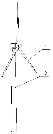
[0053] Such as figure 1 Shown: a blade for wind power generation, including a wind turbine column 3 and a blade body 1 arranged on the wind turbine column 3, divided into multiple sections in length according to the shape of the blade, each section is made of a metal plate 2, and the metal plate The number depends on the length of the blade body 1 and the length of the metal plate. Multiple metal plates are spliced ​​to form the overall structure of the blade.

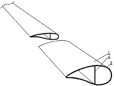
[0054] Such as figure 2 As shown: in this embodiment, the metal plate 2 includes a first panel 21, a second panel 22 and a plurality of hollow tubes 23 arranged between the first panel and the second panel, the hollow tubes 23 are connected to the first panel 21, the second panel A brazing layer is provided between the two panels 22; flanges 25 are provided at both ends of the hollow tube 23, and a circular structure is turned outward. The flanging 25 of the hollow tube is brazed with the first panel and the second...

Embodiment 2

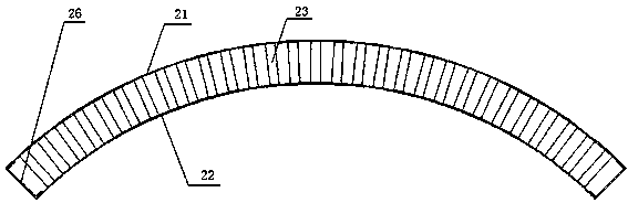
[0063] Such as Figure 6 As shown: the difference from Embodiment 1 is that the wind turbine column 3 is also formed of a cylindrical structure by arc-shaped metal plates 2, and the multiple metal plates are connected into one body by welding. The structure of the metal plate is the same as that of Embodiment 1, and will not be repeated here.

Embodiment 3

[0065] Such as Figure 7 Shown: The difference from Embodiment 1 is that when two adjacent metal plates are connected, for example, when the first metal plate 2-1 is connected to the second metal plate 2-2, the first metal plate 2-1 One panel extends along the first frame 26-1, and the second panel connects a part of the first frame 26-1; the first panel on the second metal plate 2-2 connects a part of the second frame 26-2, and the second metal The second panel on board 2-2 extends along the second border 26-2. The second frame is also integrally welded with the first frame, and the extended part of the first panel of the first metal plate is welded with the second frame and reinforced by bolts 5; the extended part of the second panel of the second metal plate is connected with the second frame The first frame is welded and reinforced by bolts 5 so as to realize the connection between two adjacent metal plates.


PUM


Abstract

The invention discloses a wind power generation blade. The wind power generation blade comprises a blade body; the blade body consists of multiple metal plates through assembly; the metal plates comprises a first panel, a second panel, and multiple hollow pipes arranged between the first panel and the second panel; connecting layers are arranged between the hollow pipes and the first panel, the second panel; and flanges are arranged on at least one ends of the hollow pipes. The wind power generation blade has the advantages of low deadweight, high strength, high rigidity, stable structure, sound insulation, noise reduction, high-temperature resistance, corrosion resistance, vibration resistance, long service life, short construction period and the like.

Description

technical field [0001] The invention relates to the technical field of wind power generation, in particular to a blade for wind power generation. Background technique [0002] Wind generators are usually installed in coastal areas with strong winds. The wind speed of the gas natural wind is used as kinetic energy to blow the blades to rotate, and the kinetic energy of the blades to rotate the generator to generate electricity. [0003] With the development of the wind power industry, the requirements for blades are getting higher and higher. For blades, strength and stiffness are very important indicators. Studies have shown that the stiffness of carbon fiber (carbon fiber, CF) composite blades is two to three times that of FRP composite blades. Although the performance of carbon fiber composites is much better than that of glass fiber composites, it is expensive, which affects its wide application in wind power generation. Therefore, the world's major composite material ...

Claims


Application Information

Patent Timeline
Patent Type & Authority Applications(China)
IPC IPC(8): F03D1/06
CPCF03D1/0675Y02E10/72
Inventor 张跃
Owner 张跃
Why Eureka
Try Eureka