Gas output pipeline of liquid natural gas storage tank

A technology for liquefied natural gas and output pipelines, applied in fixed-capacity gas storage tanks, gas/liquid distribution and storage, container discharge methods, etc., can solve problems such as accelerating heat conduction and reducing frost, so as to speed up heat conduction, reduce frost, and heat uniform effect

Inactive Publication Date: 2020-02-07
北京东方通捷燃气有限责任公司
View PDF6 Cites 0 Cited by
  • Summary
  • Abstract
  • Description
  • Claims
  • Application Information

AI Technical Summary

Problems solved by technology

[0010] Through the above technical solution, the gas output pipeline conducts heat to the liquid natural gas inside it, and the liquid natural gas is heated and vaporized to absorb heat, the temperature of the gas transmission pipeline decreases, and the air near the outer surface of the gas output pipeline conducts heat to the gas output pipeline, After the air temperature drops, the density increases, and the cold air flows downward along the surface of the steady flow part under the action of gravity. The vortex or turbulence generated by the cold air under the bottom surface of the steady flow part is relatively small, which can reduce the cold air below the bottom surface of the gas output pipe. The hot air can conduct heat to the gas output pipe faster, reduce the frost condensed on the surface of the gas output pipe, and then accelerate the heat conduction of the hot air to the gas output pipe, forming a virtuous cycle; the liquid natural gas inside the gas output pipe can be released in time Improve the problem that the increase of liquid natural gas cannot be vaporized in the gas output pipeline after it is filled with gas output pipeline

Method used


Image

  • Gas output pipeline of liquid natural gas storage tank
  • Gas output pipeline of liquid natural gas storage tank
  • Gas output pipeline of liquid natural gas storage tank

Examples


Embodiment 1

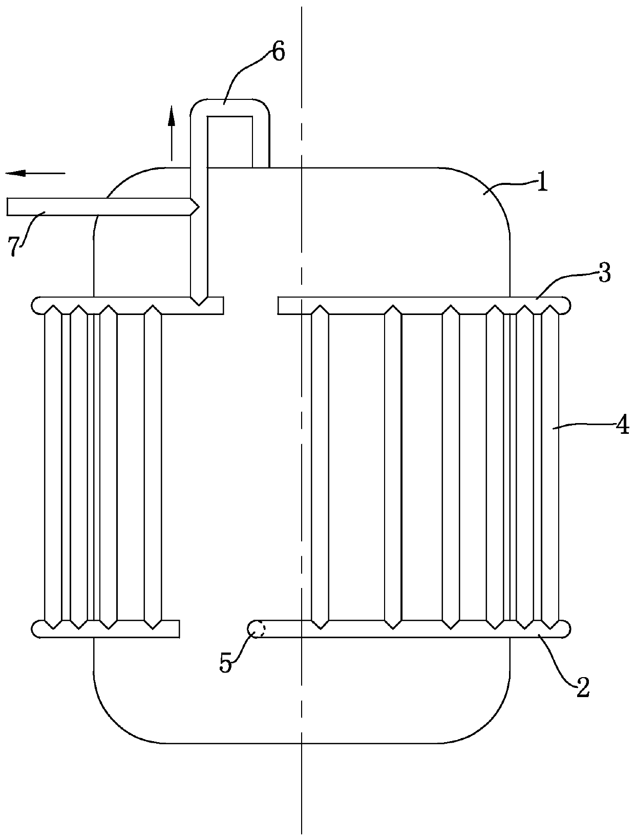
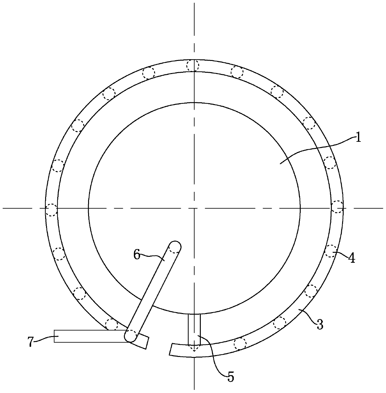
[0049] In order to facilitate the understanding of the present invention, the structure and working principle of the prior art will be briefly described first. Such as figure 1 and figure 2 As shown, the liquid natural gas storage tank 1 is surrounded by a gas outlet pipe assembly. The gas outlet pipe assembly includes a horizontally arranged gas outlet pipe 2 and an upper outlet pipe 3. Both the gas outlet pipe 2 and the upper outlet pipe 3 have disconnected gaps. The ring shape is arranged around the liquid natural gas storage tank 1; a transition pipe 4 is provided between the gas output pipe 2 and the upper output pipe 3, and the gas output pipe 2 and the upper output pipe 3 are connected through the transition pipe 4, and the transition pipe 4 are vertically arranged, and there are multiple transition pipes 4 that are evenly distributed around the circumference of the liquid natural gas storage tank 1. One end of the gas output pipe 2 is fixedly connected with a lower ...

Embodiment 2

[0063] The difference from Example 1 is that, as Figure 7 and Figure 8As shown, the heat conduction plate 23 is a hollow structure, and the inner cavity of the heat conduction plate 23 is filled with a coolant (in order to make the connection relationship between the components of the accompanying drawings clearer, the coolant is not shown in the figure), and the coolant has a relatively Liquid or gas with high thermal conductivity, if liquid is used, antifreeze coolant or cooling oil can be used, and the gas output pipeline 2 can quickly conduct heat to the position of the heat conducting plate 23 near the center of the gas output pipeline 2 through the coolant, so that the heat conduction The plate 23 quickly conducts heat to the LNG at different positions inside the gas output pipeline 2, so that the different positions of the LNG inside the gas output pipeline 2 are heated evenly, and the gasification speed of the LNG is increased.

[0064] The gas output pipe is provid...

Embodiment 3

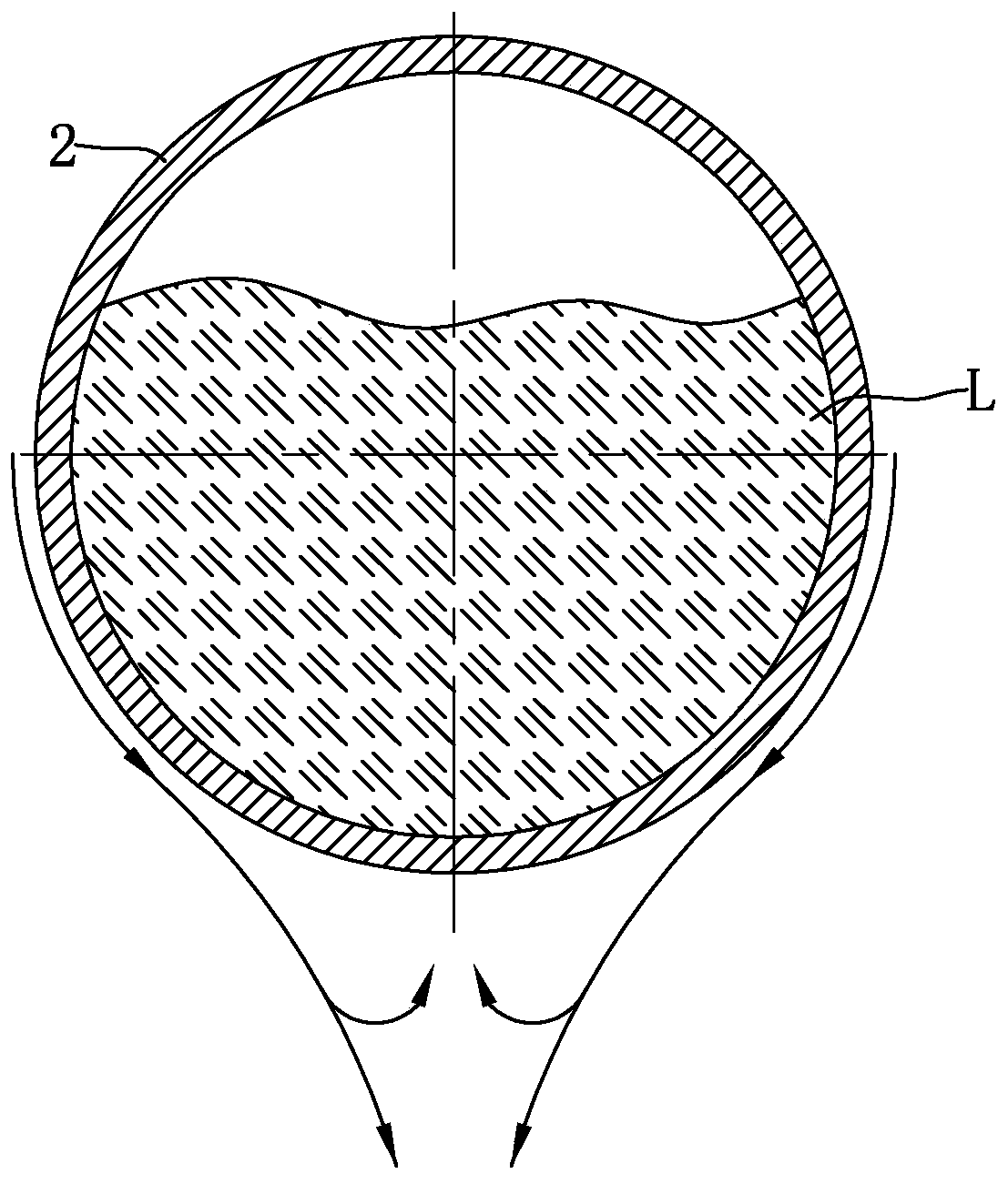
[0066] The difference from Example 2 is that, as Figure 9 As shown, due to the increase of the gasification speed of the liquid natural gas inside the gas output pipeline 2, the gas output pipeline 2 will not be filled due to the increase of the liquid natural gas, and the transition pipe 4 can be set as one; the transition pipe 4 and the gas output pipeline 2 The end away from the lower connecting pipe 5 is fixedly connected, which can increase the path length of the liquid natural gas or gas from the lower connecting pipe 5 to the transition pipe 4, and the liquid natural gas or gas can absorb more from the air during the movement in the gas output pipe 2. Lots of heat. combine Figure 10 , liquid natural gas ( Figure 10 The L refers to the liquefied natural gas) enters the gas output pipeline 2 after being gasified, and the volume of the gas increases after being heated, and the air pressure increases; the liquefied natural gas inside the liquefied natural gas storage t...


PUM


Abstract

The invention discloses a gas output pipeline of a liquid natural gas storage tank. The gas output pipeline is horizontally arranged, the upper part of the cross section of the gas output pipeline isarc-shaped, and the lower portion of the cross section of the fuel gas output pipeline is provided with a flow stabilizing portion gradually reduced in the direction away from the upper portion; and the gas output pipeline is used for conducting heat to the liquid natural gas inside the gas output pipeline, the liquid natural gas is heated and gasified to absorb heat, the temperature of the gas conveying pipeline is reduced, the air close to the outer surface of the gas output pipeline is used for conducting heat to the gas output pipeline, the density of the air is increased after the temperature of the air is reduced, the cold air flows downwards along the surface of the flow stabilizing portion under the action of gravity, the vortex or turbulence generated by the cold air under the bottom surface of the flow stabilizing portion is relatively small, so that the retention of cold air under the bottom surface of the gas output pipeline can be reduced; and heat can be transferred to the fuel gas output pipeline more quickly, so that frost condensed on the surface of the fuel gas output pipeline is reduced, and therefore the heat conduction of the hot air to the fuel gas output pipeline is accelerated, and a virtuous cycle is formed.

Description

technical field [0001] The invention relates to a liquid natural gas storage tank, in particular to a gas output pipeline of the liquid natural gas storage tank. Background technique [0002] The liquid natural gas storage tank is referred to as the LNG storage tank. It is a double-layer structure. There is a vacuum between the inner tank and the outer layer. [0003] In the existing technology, such as figure 1 and figure 2 As shown, the liquid natural gas storage tank 1 is surrounded by a gas outlet pipe assembly. The gas outlet pipe assembly includes a horizontally arranged gas outlet pipe 2 and an upper outlet pipe 3. Both the gas outlet pipe 2 and the upper outlet pipe 3 have disconnected gaps. It is circular and arranged around the liquid natural gas storage tank 1; the gas output pipe 2 and the upper output pipe 3 are connected through a transition pipe 4, and the transition pipe 4 is vertically arranged, and the transition pipe 4 has multiple and surrounds the liq...

Claims


Application Information

Patent Timeline
Patent Type & Authority Patents(China)
IPC IPC(8): F17C7/04F17C13/00
CPCF17C7/04F17C13/00F17C2221/033
Inventor 于俊杨剑刘晓宇
Owner 北京东方通捷燃气有限责任公司
Why Eureka
Try Eureka