

Minimally invasive catheter type synchronous cardiac auxiliary device and use method thereof
A heart assisting and catheter technology, applied in applications, electrocardiography, and other medical devices, can solve problems that do not conform to the physiological characteristics of the human body's own pulsation, and achieve flexible power transmission, easy popularization and promotion, and high compatibility Effect
- Summary
- Abstract
- Description
- Claims
- Application Information
AI Technical Summary
Problems solved by technology
Method used
Image

Examples
Embodiment 1
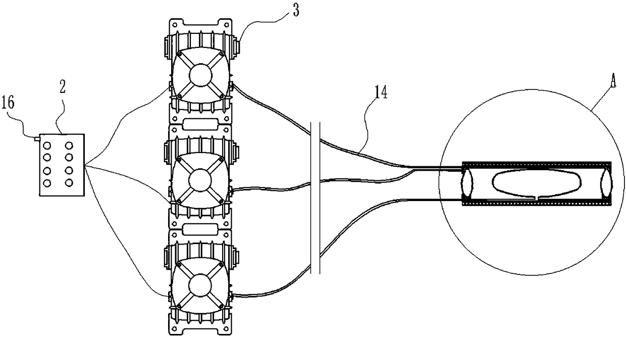
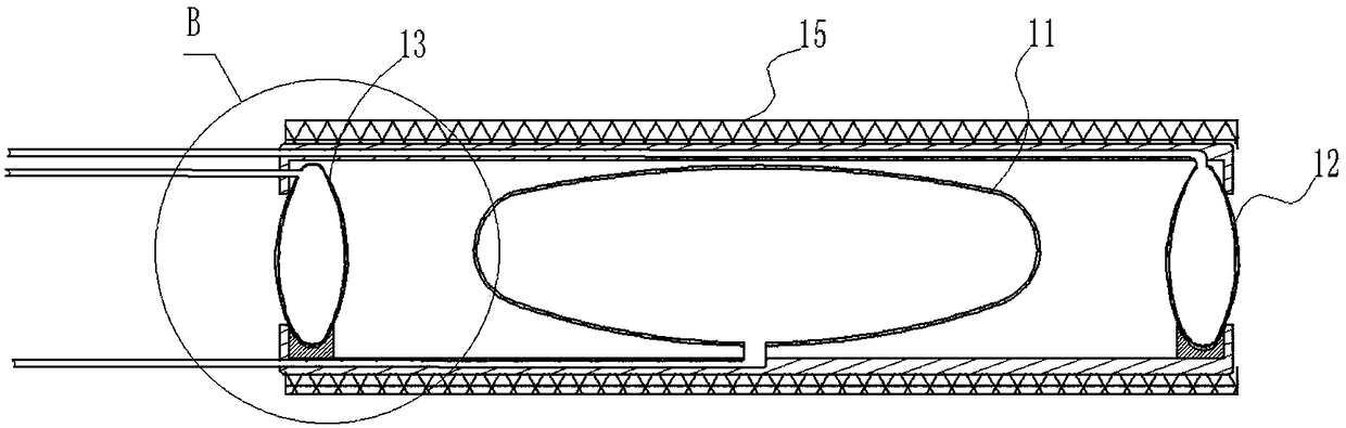
[0036] Such as figure 1 and figure 2 As shown, a minimally invasive catheter-type synchronous heart assist device includes an actuator 1 and a control module 2. The actuator 1 includes an overall cylindrical lumen enclosed by the cavity wall, and the enclosed lumen is used for placing The middle airbag 11 is provided with a front end airbag 12 and a rear end airbag 13 which are used to act as valves at the front and rear ends of the inner chamber respectively. 1 Controlled by the control module 2 and adapted to the patient's heart beat characteristics to lift blood from the left ventricle to the aorta.
[0037] Ventricular assist device is recognized worldwide as the most effective treatment for various types of end-stage heart failure. From the development of the first generation pneumatic blood pump and the second generation axial flow blood pump in the 1960s to the third generation suspension blood pump today, several generations of scientists have experienced the arduou...
Embodiment 2
[0049] Such as Figure 4 , Figure 5 As shown, the content of this embodiment is basically the same as that of Embodiment 1, and the similarities will not be repeated. The difference is that the hoses 14 of the air pump 3 outside the middle airbag 11 and the front end airbag 12 are attached to the cavity wall respectively. In this way, the structure of the present invention can be further reduced to facilitate installation and manufacture, thereby reducing production costs and facilitating popularization and use.
Embodiment 3
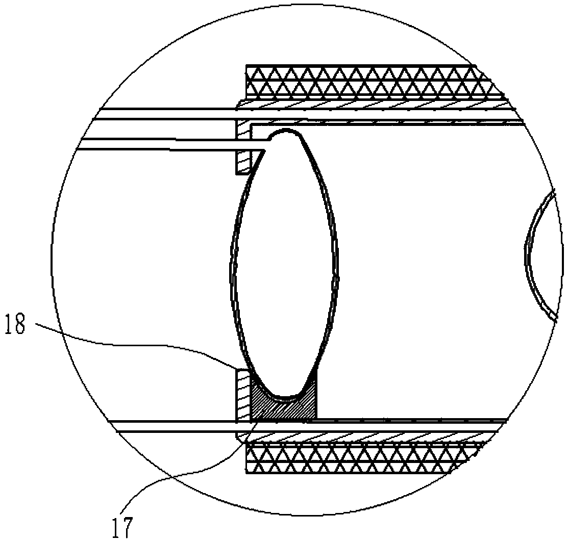
[0051] Such as Figure 6 , Figure 7 As shown, the content of this embodiment is basically the same as that of Embodiment 2, and the similarities will not be repeated. The difference is that the front end airbag 12 and the rear end airbag 13 are inflated and inflated, and the inner cavity is interference fit, and the inflated front end The airbag 12 and the rear end airbag 13 are squeezed against the cavity wall to realize the valve action. In this way, the structure of the present invention is simpler and more compact, and the volume of the inner cavity is larger without the concave stopper 17, so that the work of the actuator 1 higher efficiency.
PUM
 Abstract
Description
Claims
Application Information