

Flexible Resistive Strain Sensors
A resistive strain sensor technology, applied in the field of strain sensors, can solve the problem of small temperature coefficient of resistance of metal glass, achieve the effects of inhibiting bacterial growth, high sensitivity, and wide application fields
- Summary
- Abstract
- Description
- Claims
- Application Information
AI Technical Summary
Problems solved by technology
Method used
Image

Examples
preparation example 1
[0047] Preparation Example 1: Preparation of Zr 55 Cu 30 Ni 5 al 10 Flexible Resistive Strain Sensor with Metallic Glass Thin Film as Strain Sensitive Material
[0048] Zr, Cu, Ni, and Al metal elements with a purity of 99.99% are produced in a copper mold suction casting method according to the ratio of 11:6:1:2 (atomic percentage) 55 Cu 30 Ni 5 al 10 Sheet metal glass.
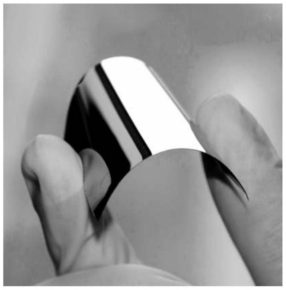
[0049] Then with this Zr 55 Cu 30 Ni 5 al 10 Plate-shaped metallic glass (amorphous alloy) was used as the deposition target, and was deposited on a pre-cleaned 0.1mm thick glass by ion beam deposition (the ion energy was 750eV during deposition, the particle beam current was 30mA, and the deposition time was 3600s). Deposited Zr with a thickness of 350nm on polycarbonate flexible substrate 55 Cu 30 Ni 5 al 10 The metal glass film, made flexible resistive strain sensor I.
[0050] The optical photo of the flexible resistive strain sensor I is as figure 1 shown. The sensor can be easily bent...
preparation example 2
[0067] Preparation Example 2: Preparation of Zr 50 Cu 50 Flexible Resistive Strain Sensor with Metallic Glass Thin Film as Strain Sensitive Material
[0068] After suction casting of copper mold is selected, the composition is Zr 50 Cu 50 The metal alloy is used as the deposition target, by ion beam deposition (the ion energy is 750eV during deposition, the particle beam current is 30mA, and the deposition time is 600s), on the pre-cleaned polycarbonate flexible substrate with a thickness of 0.1mm Deposit Zr with a thickness of 60nm 50 Cu 50 Metallic glass thin film, made flexible resistive strain sensor II.
[0069] The test process of the relationship between the resistance change rate and the strain of the sensor II is the same as that of the sensor I. Measurement results such as Figure 10 As shown, the resistance of the flexible strain sensor increases with the increase of strain, and there is a good linear relationship between the resistance change rate and strain...
preparation example 3
[0070] Preparation Example 3: Preparation of Pd 40 Cu 30 Ni 10 P 20 Flexible Resistive Strain Sensor with Metallic Glass Thin Film as Strain Sensitive Material
[0071] The selected component is Pd 40 Cu 30 Ni 10 P 20 Metallic glass (amorphous alloy) is used as the deposition target, and the ion beam deposition method (the ion energy is 750eV during deposition, the particle beam current is 30mA, and the deposition time is 600s), on the pre-cleaned polycarbonate with a thickness of 0.1mm Deposited Pd with a thickness of 60 nm on ester flexible substrates 40 Cu 30 Ni 10 P 20 Metallic glass film to make a flexible resistive strain sensor Ⅲ.
[0072] The test process of the relationship between the resistance change rate and strain of sensor III is the same as that of sensor I. Measurement results such as Figure 11 As shown, the resistance of the flexible strain sensor increases with the increase of strain, and there is a good linear relationship between the resistan...
PUM
| Property | Measurement | Unit |
|---|---|---|
| thickness | aaaaa | aaaaa |
| gauge factor | aaaaa | aaaaa |
Abstract
Description
Claims
Application Information