Precision defocus detection device and method

A technology of defocus detection and detection method, which is applied in the direction of measuring devices, optical devices, instruments, etc., can solve problems such as low precision, complicated operating devices, and difficulty in meeting system requirements, and achieve low cost, high measurement accuracy, and dynamic The effect of a large measuring range

Active Publication Date: 2018-07-27
SHANGHAI INST OF OPTICS & FINE MECHANICS CHINESE ACAD OF SCI
View PDF10 Cites 7 Cited by
  • Summary
  • Abstract
  • Description
  • Claims
  • Application Information

AI Technical Summary

Problems solved by technology

These two methods are not high in precision, and the second method has a complicated operating device. When a mi

Method used


Image

  • Precision defocus detection device and method
  • Precision defocus detection device and method
  • Precision defocus detection device and method

Examples


Embodiment 1

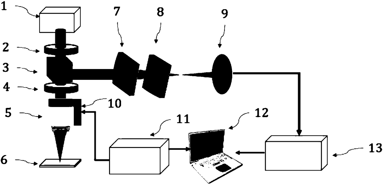
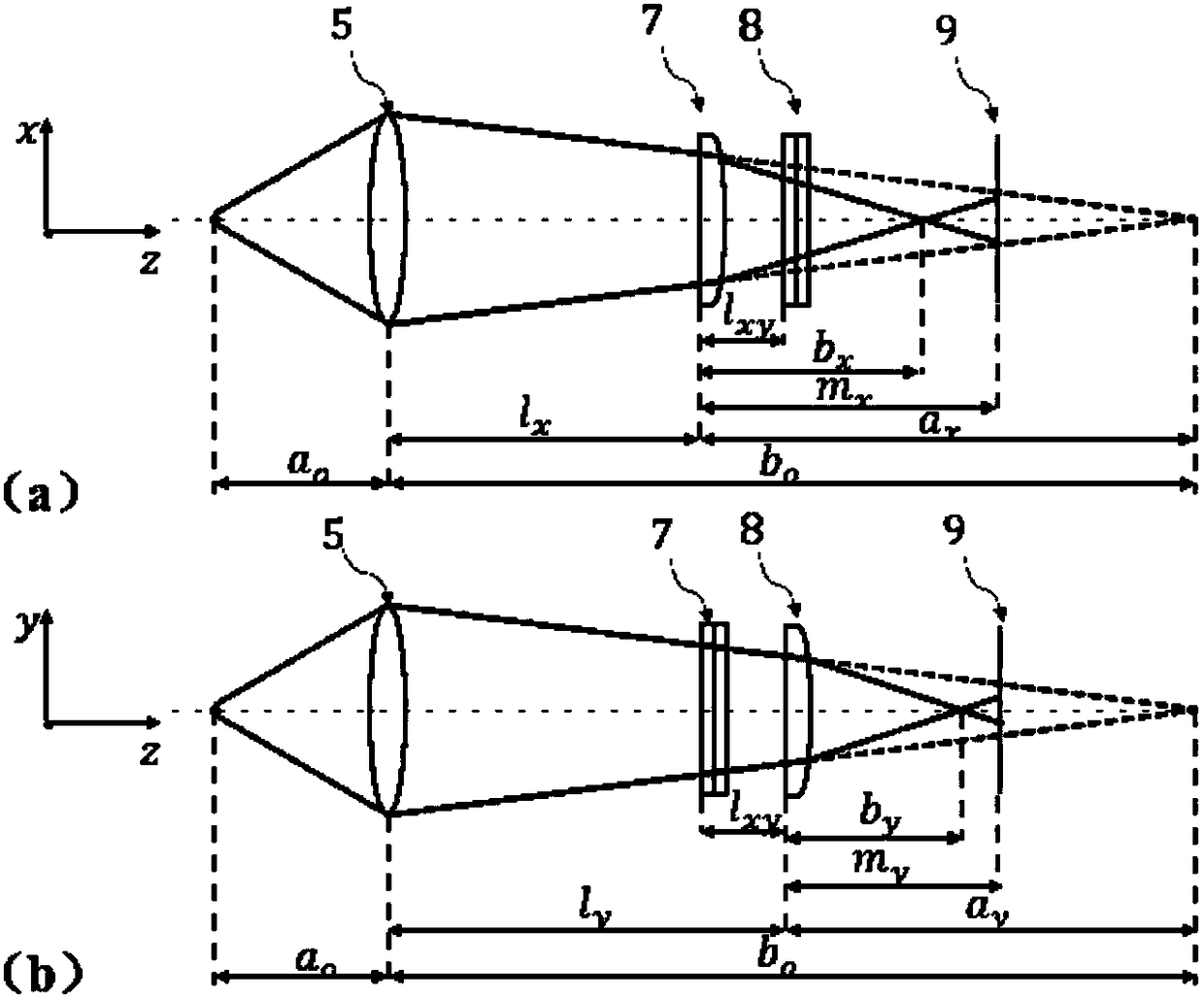
[0056] A new type of system defocus detection device and detection method, including a laser 1, a 1 / 2 wave plate 2, a polarization beam splitter prism 3, a 1 / 4 wave plate 4, a microscope objective lens 5, an aluminum film sample 6, and a cylindrical lens CL x 7. Cylindrical mirror CL y 8. Four-quadrant detector 9, piezoelectric ceramic actuator 10, piezoelectric ceramic controller 11, computer 12, controller 13, etc.: such as figure 1 As shown, the laser 1 emits parallel light with a wavelength of 658nm, then passes through the 1 / 2 wave plate 2, the polarization beam splitter 3, and the 1 / 4 wave plate 4, and then enters the microscope objective lens 5, and finally focuses on the aluminum film sample 6 . The laser light is reflected by the aluminum film sample 6, returns along the optical path, and then reflected by the polarizing beam splitter prism 3, and passes through the cylindrical mirror CL x 7 and cylindrical mirror CL x 8 are converged onto a four-quadrant detec...


PUM


Abstract

Disclosed is a precision defocus detection device and method. The method comprises the steps of constructing a defocus detection light path, implementing a defocus detection algorithm, detecting and compensating for the defocus amount, recording data and the like. According to the requirement for dynamic range and precision of a system, different light paths are designed, different micro-objectives and cylindrical mirrors are selected, and the different precisions and dynamic ranges can be obtained by changing the distance among the micro-objectives, the two cylindrical mirrors and a four-quadrant detector. When a sample is defocused, light spot patterns reflected on the detector change, formed defocused error signals change, and the precise defocusing amount is obtained through the relation between the defocusing amount and the defocusing error signals. The method is widely applied to defocusing detection in the fields of laser direct writing lithography and large-area microscope confocal scanning imaging, the focusing amount in the system running process can be precisely detected and compensated for in real time. The method is easy, practical and convenient to implement and has the high application value.

Description

technical field [0001] The invention relates to the fields of laser direct writing lithography and microscope large-area confocal scanning imaging, and is a precision defocus detection device and detection method. Background technique [0002] In the field of large-area laser direct writing lithography and microscope confocal scanning imaging, in order to achieve higher writing accuracy and imaging accuracy, the numerical aperture of the objective lens used in the system is very high, usually above 0.8, which leads to the focal point of the objective lens The depth is very small, usually only a few hundred nanometers. Therefore, during the operation of the system, due to the uneven placement of the sample, the vibration of the motion platform during the movement, and the interference of the external environment on the system, it will inevitably bring about the defocusing problem of the sample. , so the precise detection of the defocus amount has become a key technology and r...

Claims


Application Information

Patent Timeline
IPC IPC(8): G01B11/14
CPCG01B11/14
Inventor 白震魏劲松
Owner SHANGHAI INST OF OPTICS & FINE MECHANICS CHINESE ACAD OF SCI
Why Eureka
Try Eureka