Linear frequency modulation signal-based optical fiber optical time domain reflectometer detection system and method

A chirp signal, optical time domain reflectometer technology, applied in reflectometers for detecting backscattered light in the time domain, optical instrument testing, testing optical fiber/optical waveguide equipment, etc., can solve the problem of weak and increased detector signals Transmit signal energy and other issues to achieve the effect of improving detection sensitivity and dynamic range

Active Publication Date: 2018-07-31
GUANGXUN SCI & TECH WUHAN
View PDF4 Cites 11 Cited by
  • Summary
  • Abstract
  • Description
  • Claims
  • Application Information

AI Technical Summary

Problems solved by technology

[0004] The technical problem to be solved in the present invention is to solve the problem of weak detector signals. The traditional method is to repeat sampling and take the average to improve the detection sensitivity, and the second is to increase the energy of the transmitted signal

Method used


Image

  • Linear frequency modulation signal-based optical fiber optical time domain reflectometer detection system and method
  • Linear frequency modulation signal-based optical fiber optical time domain reflectometer detection system and method
  • Linear frequency modulation signal-based optical fiber optical time domain reflectometer detection system and method

Examples


Embodiment 1

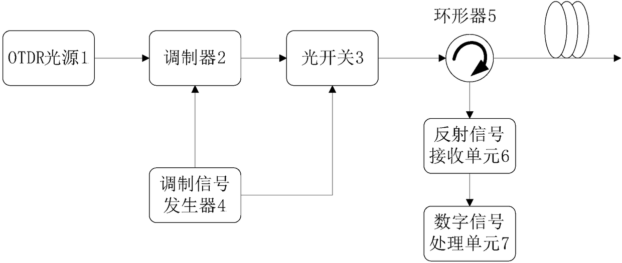
[0044] An embodiment of the present invention provides a fiber optical time domain reflectometer detection system based on a chirp signal, such as figure 1 As shown, it includes an OTDR light source 1, which is used to send out a continuous optical signal; a circulator 5, which is used to input the optical signal for detection into the transmission fiber, and input the backscattered signal into the reflected signal receiving unit 6; The signal receiving unit 6 is used to receive the backscattered signal from the transmission fiber and convert it into a digital signal.

[0045]The detection system also includes a modulation signal generator 4, a modulator 2, an optical switch 3 and a digital signal processing unit 7, wherein the modulation signal generator 4 is respectively connected to the second input port of the modulator 2 and the optical switch 3 The second input port of the OTDR light source 1 is connected to the first input port of the modulator 2, the first output port ...

Embodiment 2

[0057] In addition to providing an optical fiber optical time domain reflectometer detection system based on a chirp signal as described in Embodiment 1, the embodiment of the present invention also provides a detection method for an optical fiber optical time domain reflectometer based on a chirp signal. The detection method can be run in the detection system as described in Example 1, as shown in the figure, the method includes:

[0058] In step 201, the modulation signal generator 4 generates a chirp signal and a clock synchronization pulse, and sends them to the modulator 2 and the optical switch 3 respectively.

[0059] In step 202, the modulator 2 modulates the continuous optical signal sent by the light source according to the chirp signal to generate a continuous chirp optical signal.

[0060] In step 203, the optical switch 3 cuts the continuous chirp optical signal into a chirp optical signal of a specified time length, and inputs it into the transmission optical fib...

Embodiment 3

[0070] The embodiment of the present invention also provides a theoretically feasible implementation scheme based on the system architecture of Embodiment 1 by listing the specific product models that can be used by each module, such as Figure 4 As shown, the present invention proposes a detection device 10 of a high dynamic range OTDR based on a chirp signal. The detection device includes an OTDR light source 1, a modulator 2, an optical switch 3, a modulation signal generator 4, a circulator 5, a reflected Receiving unit 6, digital signal processing unit 7.

[0071] The OTDR light source 1 is used to send out continuous light signals.

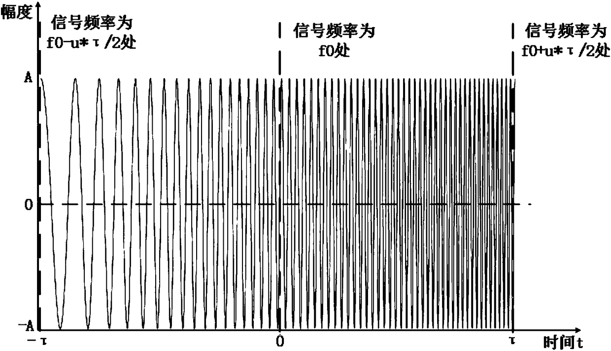
[0072] The modulation signal generator 4 is used to generate a chirp signal and a synchronous pulse signal, and the mathematical expression of the chirp signal is formula (1). Specifically, the modulation signal generator 4 may be an arbitrary waveform generator (AWG), such as Tektronix's AWG70000.

[0073] The modulator 2 is used to modul...


PUM


Abstract

The invention belongs to the optical time domain reflectometer detection technical field and provides a linear frequency modulation signal-based optical fiber optical time domain reflectometer detection system and method. The method includes the following steps that: linear frequency modulation signals and clock synchronization pulses are generated and are respectively transmitted to a modulator and an optical switch; the modulator modulates continuous optical signals emitted by a light source according to the linear frequency modulation signals so as to generate continuous linear frequency modulation optical signals; the optical switch intercepts the continuous linear frequency modulation optical signals into linear frequency modulation optical signals of specified time durations, and thelinear frequency modulation optical signals of specified time durations are inputted into a transmission optical fiber through a circulator; and fractional Fourier transformation is performed on received digital signals, so that a detection result is obtained. According to the system and method of the invention, the linear frequency modulation signals which have been subjected to the fractional Fourier transformation have high aggregation performance, and noise and nonlinear frequency modulation signals do not aggregate after being subjected to fractional Fourier transformation, and therefore, and the linear frequency modulation signals can be extracted, and the detection sensitivity and dynamic range of an OTDR (Optical Time Domain Reflectometer) can be improved.

Description

【Technical field】 [0001] The invention relates to the technical field of optical time domain reflectometer detection, in particular to an optical fiber optical time domain reflectometer detection system and method based on chirp signals. 【Background technique】 [0002] The optical time domain reflectometer is made according to the principle of backscattering and reflection of light. It uses the backscattered light generated when the light is transmitted in the optical fiber to obtain attenuation information. Understand the loss distribution of the fiber along the length, etc. Due to the uneven density of the fiber material, the uneven doping composition and the defects of the fiber itself, when the light pulse is transmitted in the fiber, it will be scattered due to the nature of the fiber itself, connectors, joints, bending or other similar events. reflection. Part of the scattered and reflected light will return to the optical time domain reflectometer, and the returned ...

Claims


Application Information

Patent Timeline
Patent Type & Authority Applications(China)
IPC IPC(8): G01M11/00
CPCG01M11/3109
Inventor 张传彬易水寒罗清夏晓文喻杰奎
Owner GUANGXUN SCI & TECH WUHAN
Why Eureka
Try Eureka