

Light and oxygen catalytic waste gas treatment system
A technology of photo-oxygen catalysis and waste gas treatment, which is applied in the direction of gas treatment, chemical instruments and methods, membrane technology, etc., can solve the problems of insufficient waste gas degradation time, poor waste gas treatment effect, insufficient waste gas degradation, etc., and achieve complete catalytic oxidation decomposition Reaction, improvement effect, uniform effect of ozone content concentration
Pending Publication Date: 2018-08-03
NINGBO UNIV
View PDF1 Cites 6 Cited by
- Summary
- Abstract
- Description
- Claims
- Application Information
AI Technical Summary
Problems solved by technology
Due to the short contact time between exhaust gas and ultraviolet rays, the degradation time of exhaust gas is insufficient, resulting in insufficient degradation of exhaust gas, so the effect of exhaust gas treatment is poor
Method used
View moreImage
Smart ImageViewing Examples

Examples
Embodiment 1
[0072] Embodiment 1: set up according to the photocatalytic reaction device in this patent;
Login to View More PUM
| Property | Measurement | Unit |
|---|---|---|
| breaking strength | aaaaa | aaaaa |
Abstract
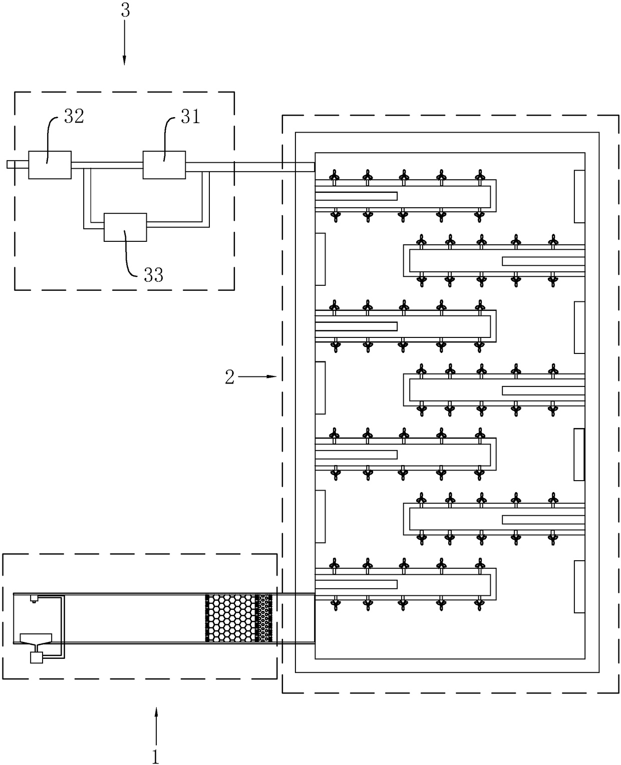
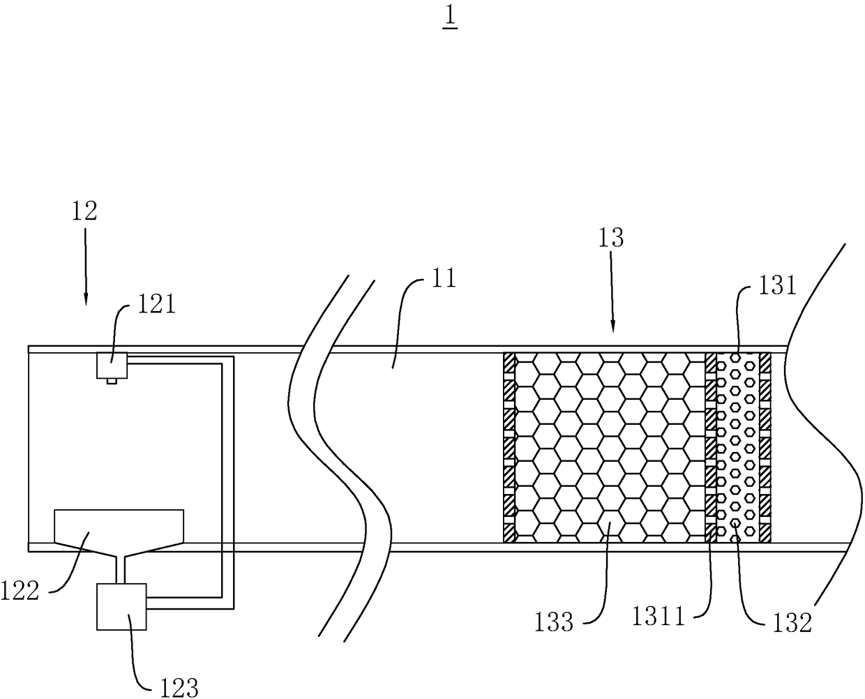
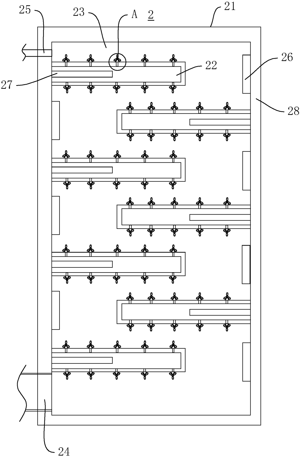
The invention relates to the technical field of waste gas treatment, in particular to a light and oxygen catalytic waste gas treatment system, and solves the problem of poor waste gas treatment effectof the waste gas treatment system in the prior art. The light and oxygen catalytic waste gas treatment system has the main technical scheme that the light and oxygen catalytic waste gas treatment system comprises a pretreatment device, a light and oxygen catalytic reaction device and a product collection device, wherein the light and oxygen catalytic reaction device comprises a casing and baffleplates in laminated crossing arrangement; an ultraviolet ray emitter is arranged in a position, right aligned with each baffle plate, on the casing; a reaction passage is formed between the baffle plate and the casing; sulfur dioxide and hydrogen sulfide in the waste gas are removed through the pretreatment device; the waste gas and the bacteria in the waste gas are cracked through the light and oxygen catalytic reaction device; through the product collection device, the generated carbon dioxide is collected, so that the waste gas is efficiently treated; the environment pollution is reduced.
Description
technical field [0001] The invention relates to the technical field of waste gas treatment, in particular to a photo-oxygen catalytic waste gas treatment system. Background technique [0002] As the country has paid more and more attention to environmental protection in recent years, waste gas treatment technology has developed vigorously, especially photo-oxygen catalytic waste gas treatment has made great progress. The photo-oxygen catalytic reaction is a reaction in which high-energy high-ozone UV ultraviolet light beams are used to irradiate the waste gas to be treated, so that the waste gas is cracked and oxidized. [0003] In the Chinese invention patent with the authorized announcement number CN202460470U, a photo-oxygen catalytic organic waste gas processor is disclosed, including a housing, an ultraviolet lamp and a filter medium. There is a filter medium between the outlet and the gas outlet, and the filter medium is loaded with nano-TiO 2 The active carbon fiber...
Claims
Login to View More Application Information
Patent Timeline
 Patent Type & AuthorityApplications(China)
IPC IPC(8): B01D53/75B01D53/78B01D53/86B01D53/52B01D53/50
CPCB01D53/04B01D53/52B01D53/75B01D53/78B01D53/8615B01D2255/802B01D2257/91
Inventor竺新波
OwnerNINGBO UNIV